Misc. Tutorial: Building a Browning 1919
(updated 09-20-2016)
This tutorial is for informational purposes only
I DO NOT SELL PARTS FOR THE 1919.
I DO NOT OFFER 1919 BUILDS.
I DO NOT HELP PEOPLE BUILD THEIR 1919s
DO NOT CALL ME ABOUT 1919s
I DO NOT SELL PARTS FOR THE 1919.
I DO NOT OFFER 1919 BUILDS.
I DO NOT HELP PEOPLE BUILD THEIR 1919s
DO NOT CALL ME ABOUT 1919s
Introduction
The following information is for legal manufacturers only. You must have your Type 7 FFL and Special Occupation Tax (SOT) to legally manufacture a 1919 right side plate in standard (full-automatic) configuration. You must have a Type 7 FFL to manufacture a semiautomatic for purpose of resale. You do not a license to manufacture a 1919 semiautomatic-only, provided it is not for purpose of resale. You do not need a license to manufacture a sideplate for a non-firing display gun. Please consult BATFE technology branch for rules on making your 1919 a non-firing display gun.
BATFE Approval Letter
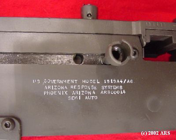
Arizona Response Systems manufactured this Browning Model 1919 A4/A6 in semiautomatic configuration. This firearm complies with Bureau of Alcohol, Tobacco, and Firearms rules as we understand them. We have made the following modifications to the standard model 1919 machinegun in accordance with the January 20, 1998 letter from Edward M. Owens, Jr., Chief, BATFE Firearms Technology Branch (F:SD:FTB:EMO 3311).
- The right sideplate is thicker than a standard model 1919 right sideplate.
(a) it is slotted to permit assembly and function with a redesigned barrel extension, lock frame and bolt.
(b) it is permanently attached to the trunion, top plate and bottom plate with deep, penetrating TIG welds (BATFE has subsequently dropped this requirement). - The trigger is redesigned to permit only a single shot to be fired each time the trigger is pulled.
(a) the trigger incorporates a return spring.
(b) the forward engagement surface of the trigger is incompatible with a standard model 1919 sear plate.
(c) the forward portion of the trigger arm is spring loaded to act as a disconnector. - The sear plate is wider than a standard model 1919 sear plate.
(a) the trigger engagement surface of the sear plate is wider than a standard model 1919.
(b) the trigger will not re-engage the sear plate unless the trigger is released after each shot is fired. - The bolt is machined to accept the above described sear plate.
(a) the machining prevents the installation of a standard model 1919 sear plate.
(b) the bolt is slotted to permit assembly and function with the redesigned right side plate. - The lock frame is redesigned
(a) a spacer is used to mount a trigger stop.
(b) a trigger return spring and a redundant trigger return plunger mount to the spacer
(c) the lock frame is slotted to permit assembly and function with the redesigned right side plate. - The accelerator is redesigned to permit assembly and function with the redesigned trigger arm.
- The barrel extension is redesigned
(a) it is slotted to permit assembly and function with the redesigned right side plate.
(b) it is relieved to permit clearance of the trigger arm.
Materials
- 1/4″ x 28 tpi tap, tapered (acceptable)
- 1/4″ x 28 tpi tap, helical flute, tear-drop shape tap (preferred)
- “E” drill bit (.2500″), high speed steel or cobalt (acceptable)
- “E “drill bit (.2500”), 2 flute carbide (preferred)
- “3” drill bit (.2130″), high speed steel or cobalt (acceptable)
- “3” drill bit (.2130″), 2 flute carbide (preferred)
- 1/4″ x 28 tpi x 3/8″ button head socket screws (18)
- 1/4″ x 28 tpi x 1/2″ button head socket screws (2)
- 1/4″ x 28 tpi x 1/2″ socket screw with 45 degree v-neck (3)
- trunion bolt (2) or trunion washer (2)
- trunion nut (2)
- trunion drill size
- pintle drill size
- lock frame plunger drill size
- top cover hinge drill size
- AR-15 trigger spring
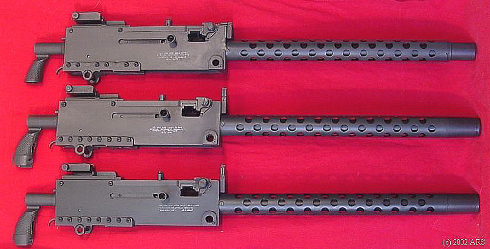
Sideplate
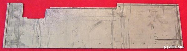
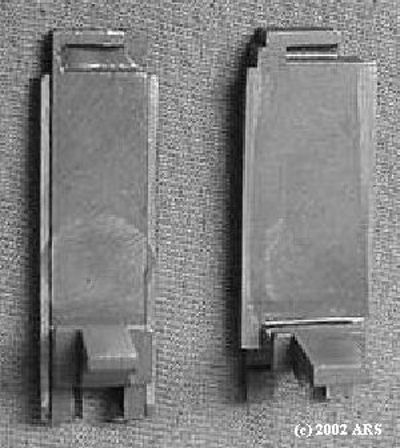
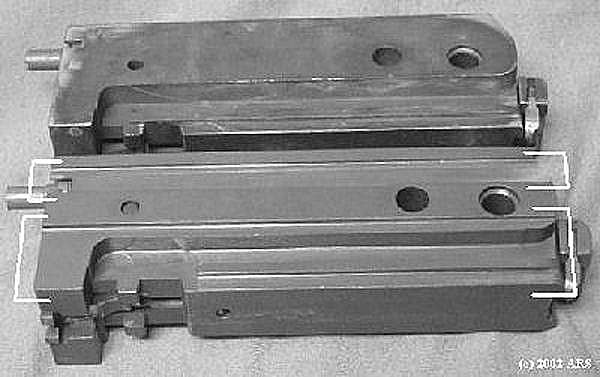
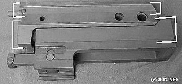
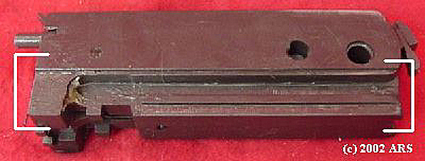
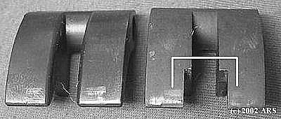
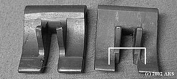
Standard 80% sideplate for manufacturing full-automatic 1919.
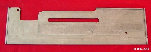
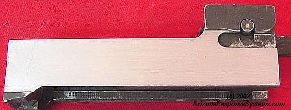
Semiautomatic 80% sideplate. Note the semiautomatic sideplate is thicker and incorporates a rail to prevent using it with an unmodified lockframe, bolt, and barrel extension.


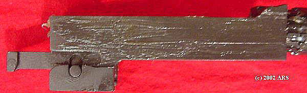
Standard right sideplate dimensions.
Trigger Group

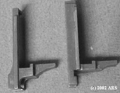
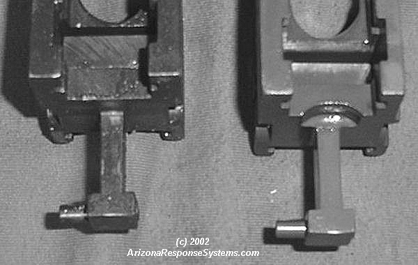
Original GI trigger compared to an early style semiauto trigger with single cross-pin.

ARS new design semiauto trigger uses two cross pins for greater support of the sliding components.

Early style used this internal spring to “push” trigger and cause disconnect.
ARS new design uses this external spring to “pull” the trigger and cause disconnect.
Bolt & Sear
Standard sear plate
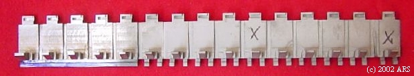
New manufacture semiauto searplate-0. Note the additional width and wider clearance for modified trigger that would completely miss an unmodified trigger.
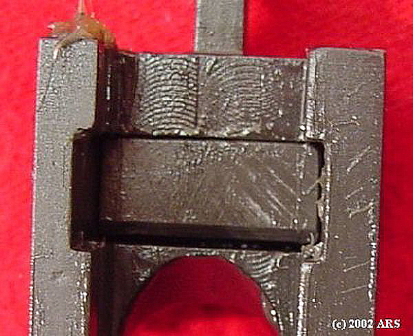
Semiauto searplate-0 installed in bolt. Note wider cut to accommodate the semiautomatic trigger
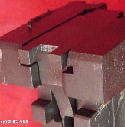
Standard bolt on top, semiautomatic bolt on bottom machined with two slots for earlier style sideplate.
Earlier style of semiauto bolt cut for sideplate with two rails (shown with barrel extension).
New simplified cut on bolt for sideplate with single rail of the type manufactured (designed?) by Lee Tool. The contour holds the lock frame, however ARS uses the hole and plunger on the trigger axis as on the original.
Lock Frame
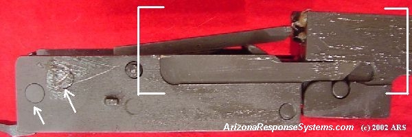
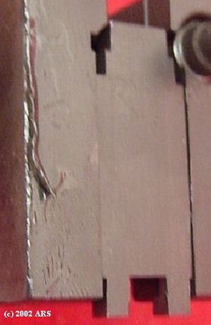
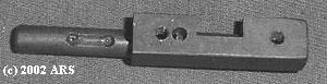
Modified lock frame with barrel extension showing machined area to fit modified sideplate. Note spacer for mounting trigger return spring and second spacer for mounting trigger disconnect spring.
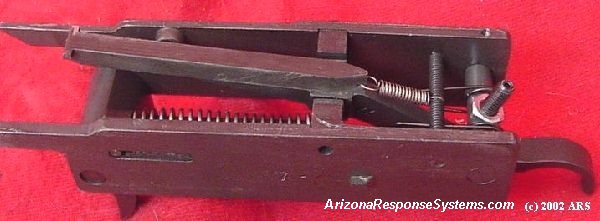
Modified lock frame showing trigger return spring and redundant plunger; spacer, and second spacer for trigger disconnect spring.
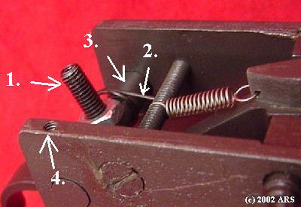
1. redundant trigger return plunger. 2. trigger return spring (AR-15 trigger spring). 3. spacer. 4. set screw to retain spacer.
Semiauto Accelerator
Semiautomatic accelerator widened to accommodate wider trigger
Barrel Extension
Semiautomatic barrel extension machined to fit semiautomatic sideplate.
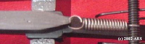
Safety
Optional cross-bolt-0 safety prevents trigger from depressing.
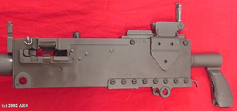
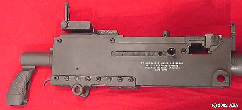
Welding Sideplate
Modified sideplate must be welded to the trunion, top plate, and bottom plate by “deep penetrating welds.” On our earlier guns we welded through a rivit/bolt hole and built the weld up to look like a rivit head. We were not satisfied with the cosmetics and subsequently went to evenly spacing the welds and leaving the head off all together. Current production we leave all the rivets (or bolts) and weld the edges of the bottom plate. By machining a groove where the weld will go, overlapping both pieces of metal, and then using argon instead of argon/C02, the welds lie flat and require little finish work. We are experimenting now with hiding the welds internally.
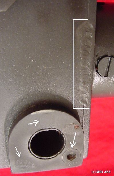
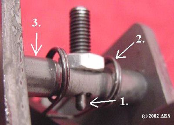
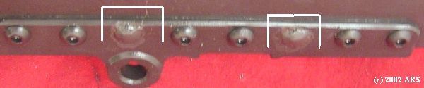
TIG welded trunion. Note rivets. V-neck screw used to fasten to trunion.
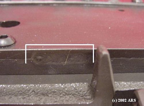
TIG welded top plate
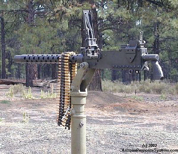
Completed 1919
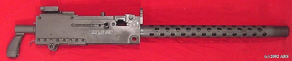
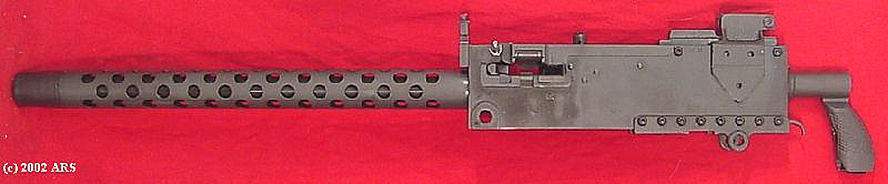
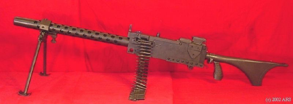
Completed 1919
Unsafe Ammunition Warning
Detonation caused by French Ammunition. Apparently, the French ammo sold by J&G had proof loads mixed in.

Rails sheared off.
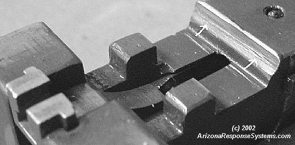
“Double bevel faces up and forward.” Battered bolt from French proof load.
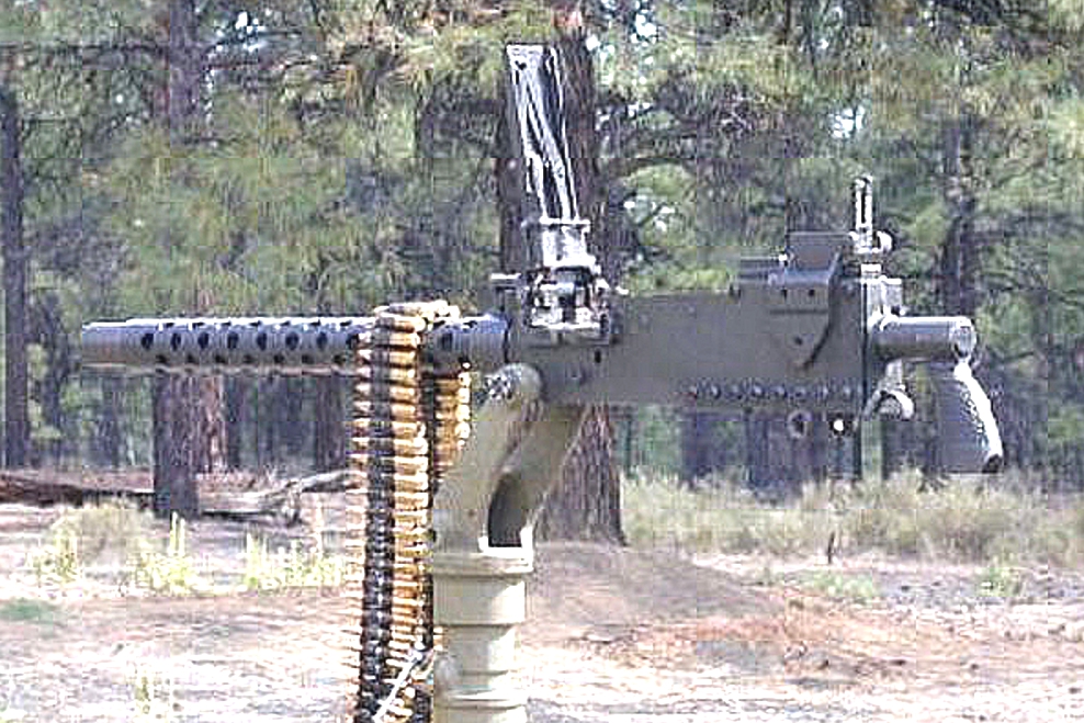
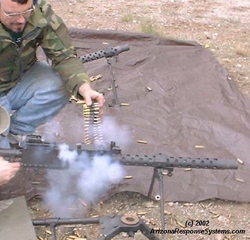
1919 in Action
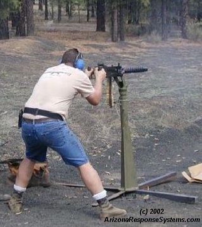
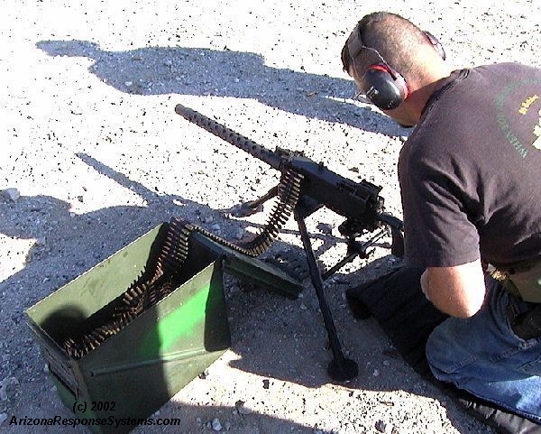
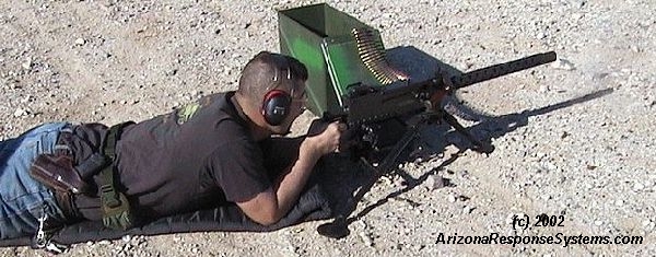
1919 in Action
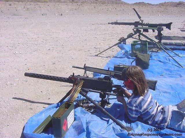
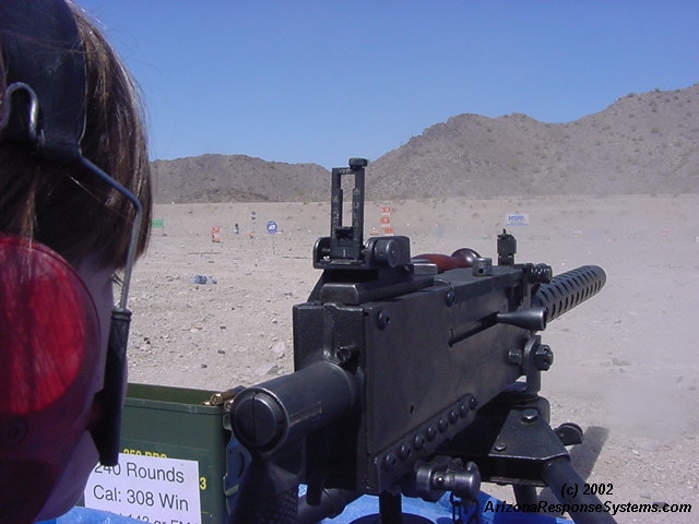
My daughter chewing up the desert. Note the muzzle blast

Leave a Reply
You must be logged in to post a comment.