Misc. Review: Czech Vz52 Rifle, Assembly & Dissassembly,
(updated 04-09-2020)
This review is for informational purposes only
I DO NOT SELL PARTS FOR THE VZ 52
DO NOT CALL ME ABOUT THE VZ 52
I DO NOT SELL PARTS FOR THE VZ 52
DO NOT CALL ME ABOUT THE VZ 52
Introduction
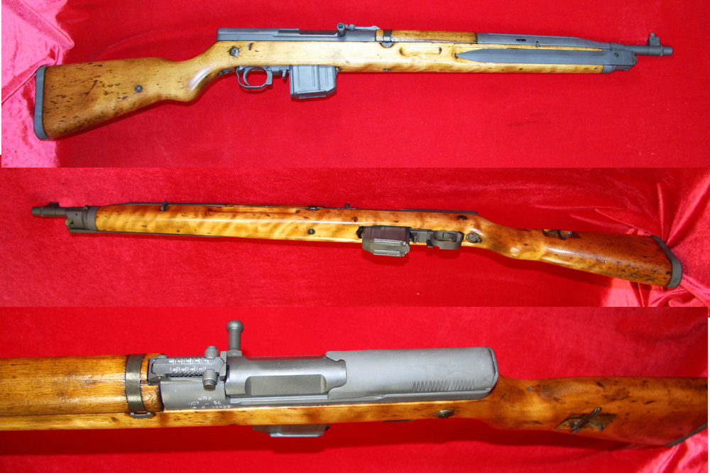
The Czechoslovakian Vzor 1952 rifle, or Vz. 52, is a magazine fed, clip-loaded, semiautomatic, gas-operated, forward-tilting bolt, infantry rifle which entered Czech military service in 1952. It fires the Czech 7.62x45mm cartridge. It was replaced with the Vz.52/57 rifle chambered in the 7.62x39mm Russian Cartridge for uniformity within the Warsaw Pact. Having a relatively short service life, the Vz 52 and 52/57 were replaced starting in 1959 with the shorter, lighter, and higher-capacity Vzor 1958, or Vz. 58, it is nonetheless an interesting rifle for collectors. Unfortunately, due to the use of corrosive-primed ammunition and difficulty in field cleaning, as well as some design weaknesses described below, it is unusual to find pristine examples on the United States collector’s market. Two arsenals produced the rifle, first Povalske Strojarne Povalska Bystrica, and then Ceska Zbrojovka Uhersky Brod. The Arsenal markings are AYM and SHE.
I acquired seven rifles that were in rather poor cosmetic condition. They were packed with grease and dirt and had the stocks spray-painted black. I decided to refinish them, but my references didn’t include an exploded view. Even Numrich Gun Parts Corp only showed major components. Hopefully these notes will assist anyone else doing a complete A&D for cleaning, repair or refinishing.
Magazine
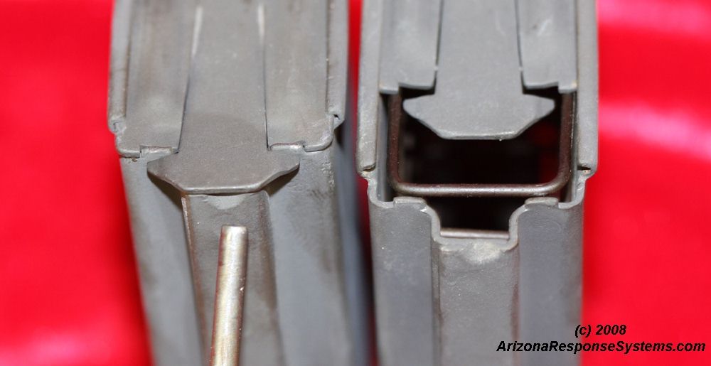
Magazine Floorplate. the magazine floorplate has a simple spring steel latch. Using a punch or the point of a bullet, raise the rear flange and slide forward.
Magazine Spring. the magazine spring is captive in the follower. Press inward and snap under the ledge of the follower. When assembled, it is possible to trap the follower on top of the magazine front, which prevents rounds from being loaded and the magazine from locking into a rifle with the bolt closed. Insure the follower depressed freely in the magazine body.
Sight Group
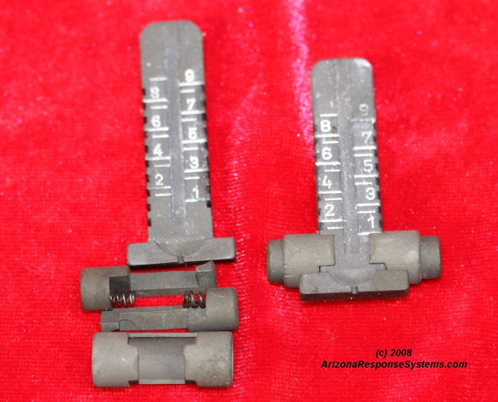
Rear Sight. The rear sight is typical of tangent-style sights. There does not seem to be a direction for installation. On some models, the sliding portion has a line on both sides of different heights, the purpose of which I am unclear. All of the sights I have seen had a range scale on the underside as well as the visible side, to what purpose I don’t know. The sight is retained in the receiver with a small leaf spring and a cross-pin. I find it easiest to use a punch to secure the sight in the receiver recess, and then drive the punch out with the retaining pin. The ends of the retaining pin have a slight flaring to prevent it from drifting out.
Bayonet Group
Bayonet Components The integral bayonet is one of the weaknesses of this rifle. The stock is thin through the center and prone to cracking there and at the wrist. If the bayonet is used, any lateral force applied to it puts considerable leverage and strain on the thinnest and weakest portion of the stock. As the hinge mechanism of the bayonet wears, it fits more loosely into the stock recess, providing a nice, sharp point on which to impale the shooters non-firing hand. While the value of the bayonet may be dubious, the mechanism is rather clever in its design. Pushing the lever on the left side frees the bayonet to pivot open. The spring for this lever is the same spring for the button on the right side. Depressing this button with the bayonet closed, through the corresponding hole in the bayonet, frees the barrel shroud. This barrel shroud slides forward and allows the upper handguard to be removed and the entire barreled-action to cam upwards and release from the retainer at the stock wrist.
Bolt Hold Open
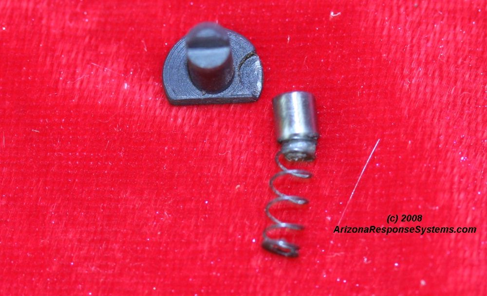
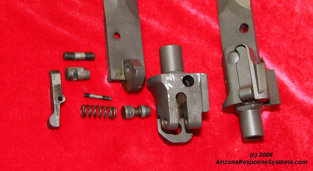
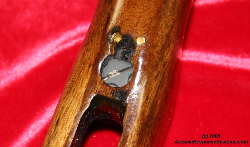
BHO Components. The bolt hold-open assembly consists of the bolt hold-open, a plunger, and a plunger spring. It is more simple than a number of other designs in that it requires no tools for assembly, although a bullet tip can make the task easier. Note the small half-circular recess in the bolt hold-open. The plunger presses against this recess to prevent the bolt hold-open from rotating. The round side of the bolt hold open protrudes into the magazine well. When the magazine is empty, the follower presses upward against this round portion, which forces the bolt to stop against the rear flat surface. After inserting a fresh magazine, the bolt handle must be retracted to release pressure from the bolt hold-open and allow the plunger and spring to snap it back down, allowing the bolt to close and chamber a fresh cartridge.
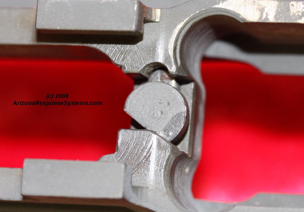
BHO Installation. One end of the plunger spring has a reduced diameter to grab the plunger. Install the plunger on this end, and insert into the hole on the underside of the receiver with the round side of the bolt hold-open pressing down on the plunger. Rotate the bolt-hold-open.
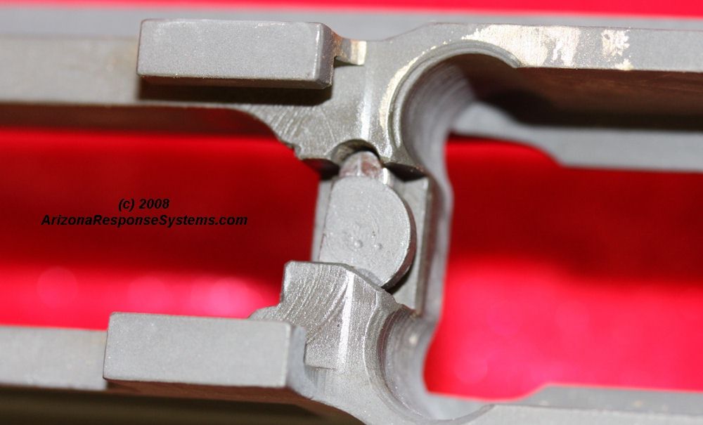
BHO Installation. Continue rotating the BHO until the round portion faces the magazine well. You should feel the slight snap of the plunger engaging its recess. Attempt to rotate the BHO. When properly assembled, it should not turn.
Trigger Group
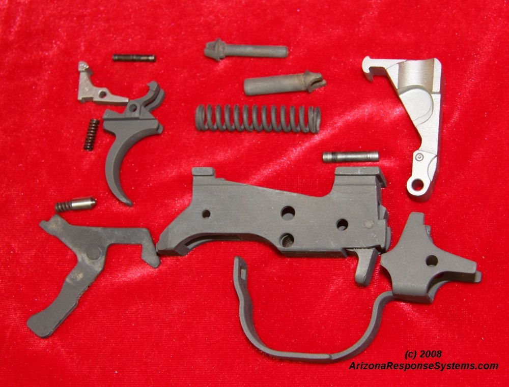
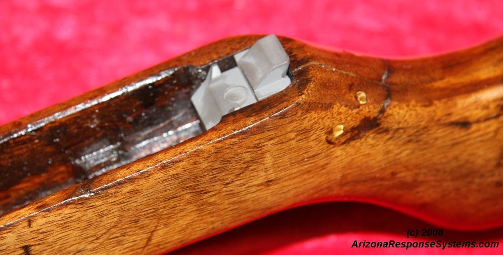
Trigger Group Components. The trigger group is simple in design with an ergonomic safety lever similar to that of the M1 Garand, M-14, and Mini-14. On safe, it protrudes into the trigger guard where it’s position is easily determined with the trigger finger. In the safe position, it blocks both the hammer from releasing and the trigger from depressing. The trigger group is removed from the receiver by pulling the trigger guard to the rear and rotating it down. The safety lever has a protrusion on the top that prevents it from being installed into or removed from the receiver rails unless it is in the safe position.
Magazine Catch. The magazine catch assembly consists of the magazine catch, spring, and axle. Installation is simple in concept, although sometimes it can be challenging to get the holes in the trigger mechanism housing and the magazine catch aligned. I find it easiest to first trap the spring on the axle (center) and then to insert a punch from the opposite side to help wiggle the catch into alignment.

Safety Lever. The safety lever assembly consists of the safety lever, the safety lever detent, and the safety lever spring. A round stub protrudes from the opposite side as the pivot point, and engages a corresponding hole in the trigger mechanism housing. Insert the spring and the detent into the trigger mechanism housing. Optionally apply a small dab of grease on the surfaces of the safety lever that will rub on the trigger mechanism housing. Insert the safety lever into the trigger mechanism housing from the top. Depress the plunger and slide the safety lever in until it catches the edge of the detent. Withdraw the punch and snap the safety lever into it’s pivot hole. Manipulate the safety into both the safe and the fire positions. It should move smoothly with a distinctive click into each position. If the safety lever is hard to move, disassemble and examine the detent point. If it is overly rounded, too much of the detent will engage the holes and make it difficult to operate. Carefully sharpening the detent point will make selector operation easier. Unfortunately, this task is by trial and error. It is better to have to test fit it several times than to have to find a new detent.
Trigger Assembly. The trigger assembly consists of the trigger, the disconnector, the disconnector spring, and the trigger axle. Install the trigger, disconnector and disconnector spring into the trigger mechanism housing and secure with the trigger axle pin. Using a slave pin or a punch to assist in alignment may ease insertion of the trigger axle pin.
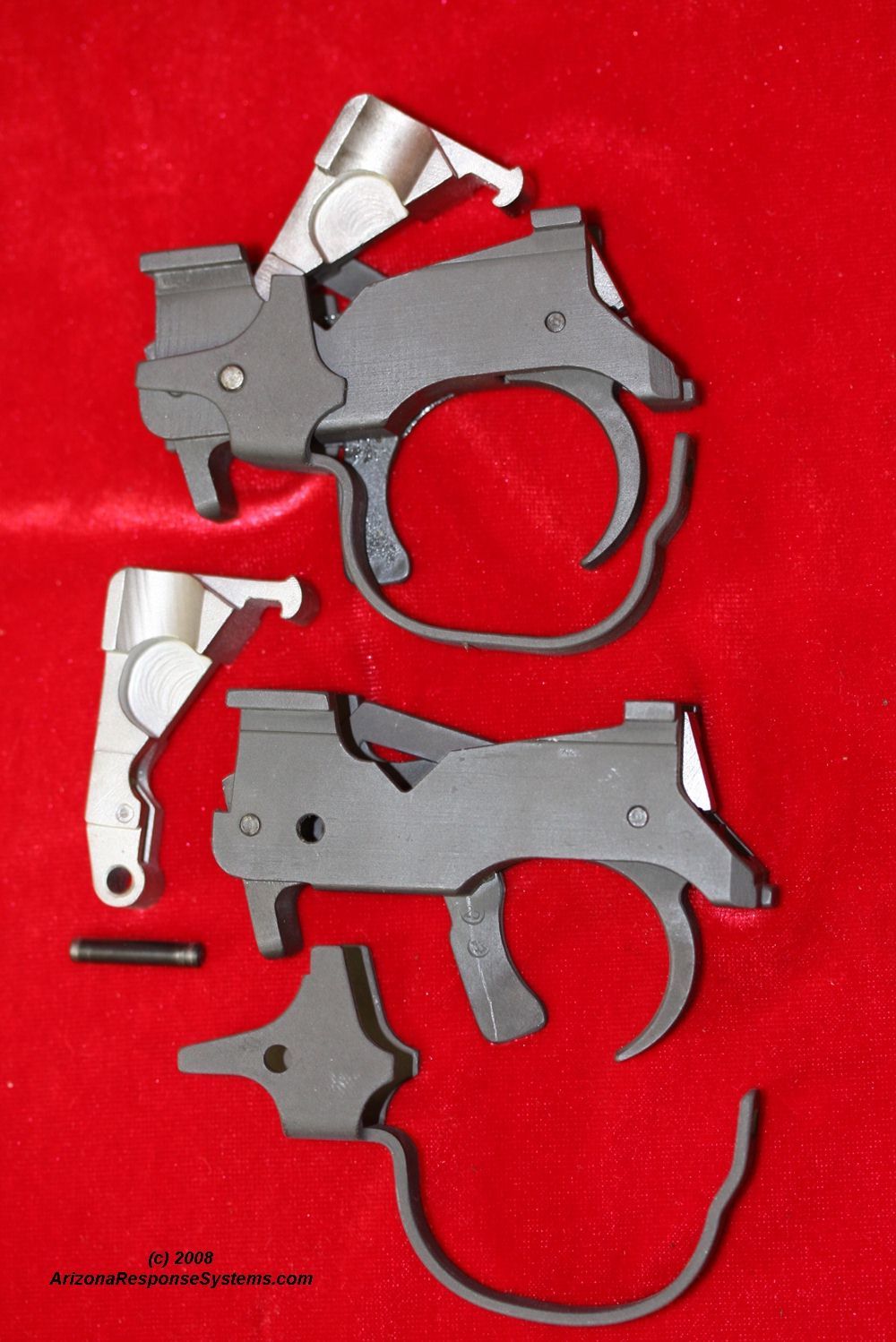
Hammer. Install the hammer under the blocking portion of the safety lever and insert the hammer axle pin.
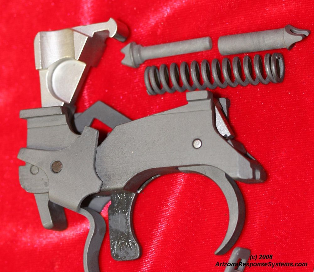
Hammer Strut Assembly. The hammer strut assembly consists of the hammer strut, the hammer spring, and the trigger strut. Insert the trigger strut into the hammer spring from one side and the hammer strut from the other.
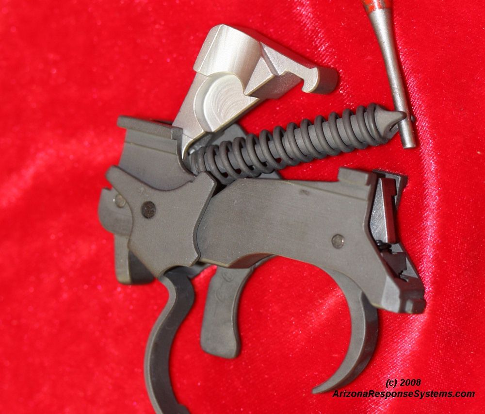
Hammer Strut Installation. Installing the hammer strut assembly is probably the most difficult part of assembling the Vz52 rifle. Insert the hammer strut (smaller side) into the cross-pin/recess at the bottom rear of the hammer. Using a punch, compress the spring by pushing the trigger side of the strut (wider end) toward the hammer until it will clear the arms of the trigger, then guide it downwards to engage it’s recess in the front of the trigger.
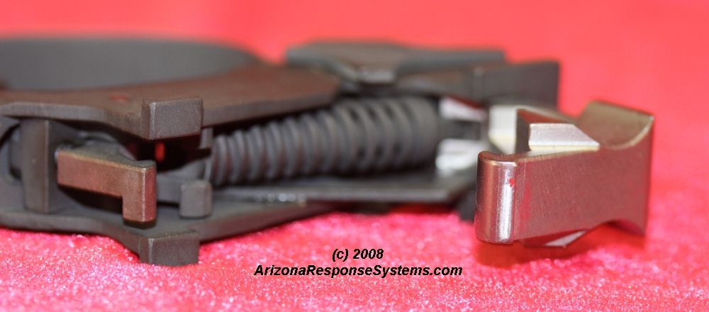
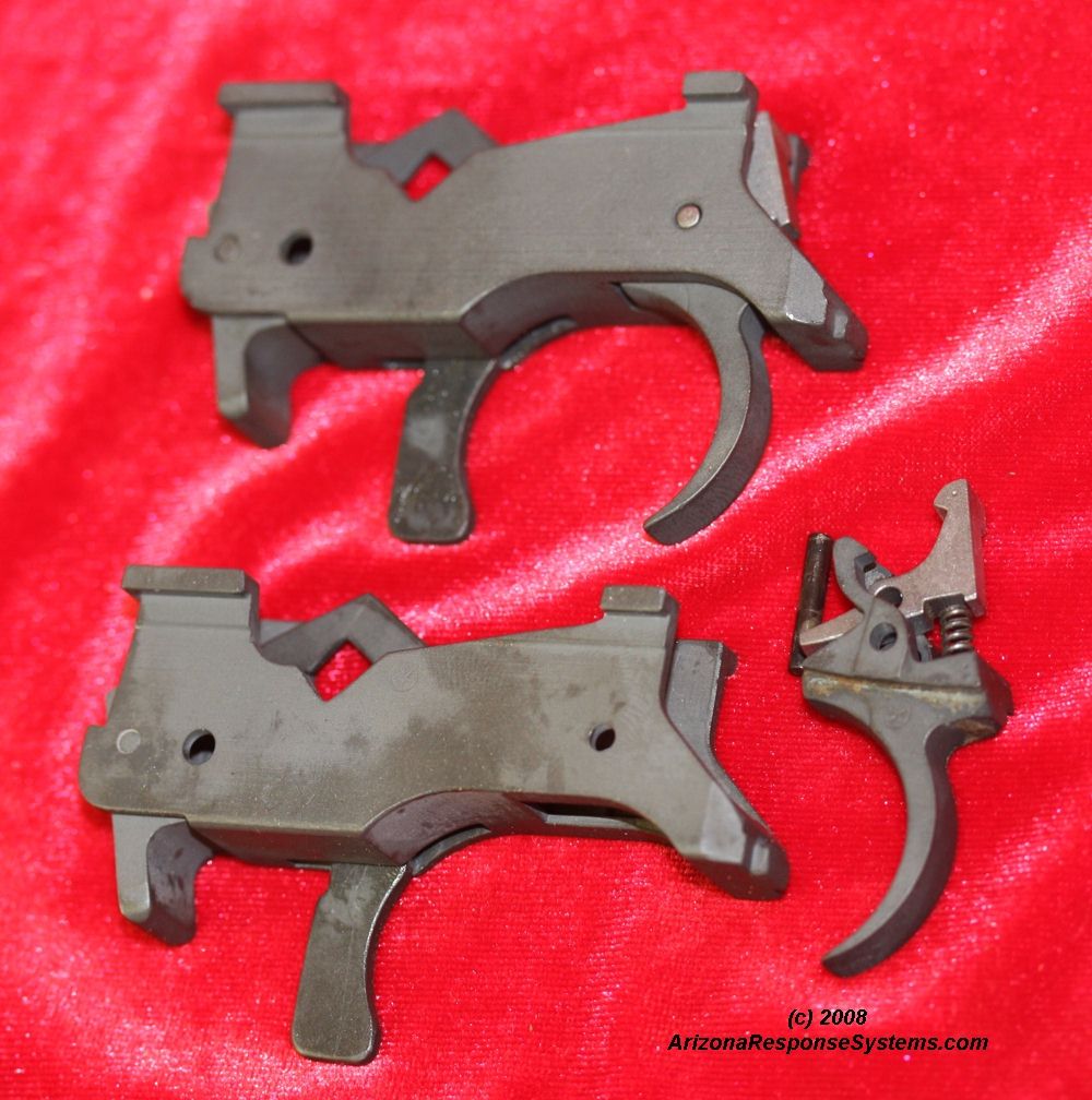
Trigger Group Assembled. Function test the trigger group to insure it will release the hammer when in the safety lever is in the fire position, and not release the hammer when the safety lever is in the the safe position. Hold the trigger back after releasing the hammer and reset the hammer. release the trigger and insure that the disconnector will release the hammer and the allow the trigger arms to catch it. If it does not release, carefully polish the top rear of the hammer where the disconnector catches.
Bolt and Carrier Group
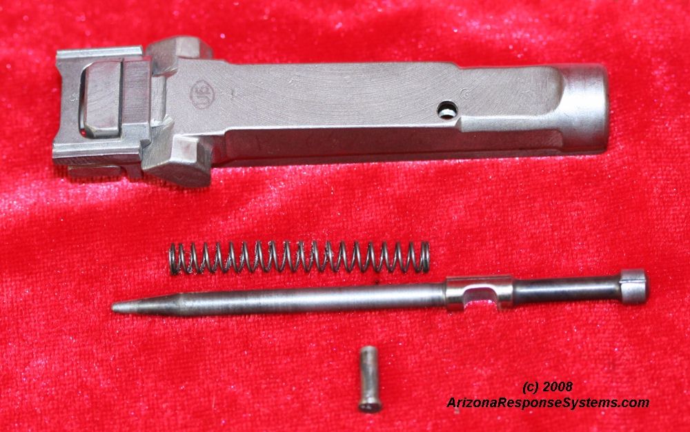
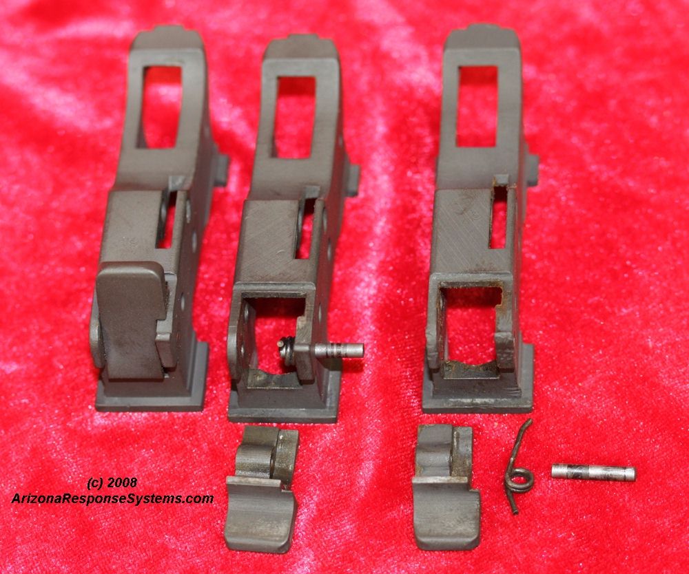
Bolt Assembly The bolt assembly consists of the extractor, bolt body, firing pin, firing pin spring, firing pin retaining pin, ejector, and ejector spring. The extractor should not be removed from the bolt as it is hardened steel and easily fractured by levering it off the bolt body.
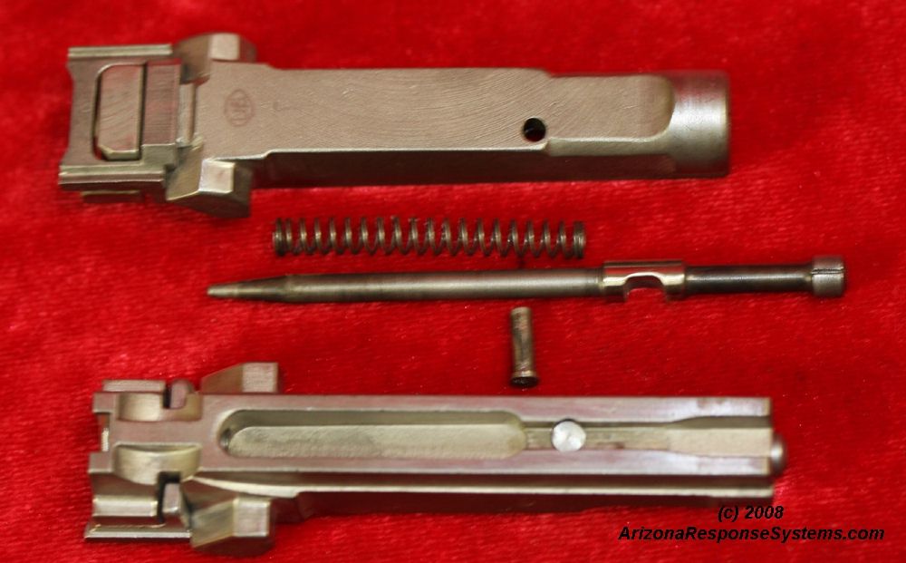
Firing Pin. Insert the firing pin into the spring and then both into the bolt body. Rotate the firing pin until the line on the firing pin matches the line on the bolt body. Manipulate the firing pin and ensure it moves freely. If it does, insert the firing pin retaining pin. If it does not, remove and examine the area where the firing pin retaining pin limits the firing pin travel. I have seen sever firing pins where there is a slight deformation on the edges of this cutout which put friction on the firing pin channel. Carefully stone these burrs flat and reassemble.
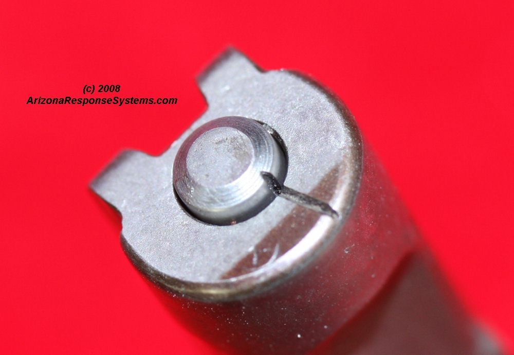
Firing Pin Alignment. Correct firing pin alignment is when the two lines meet. If the firing pin is not in this orientation, you will be unable to insert the firing pin retaining pin.
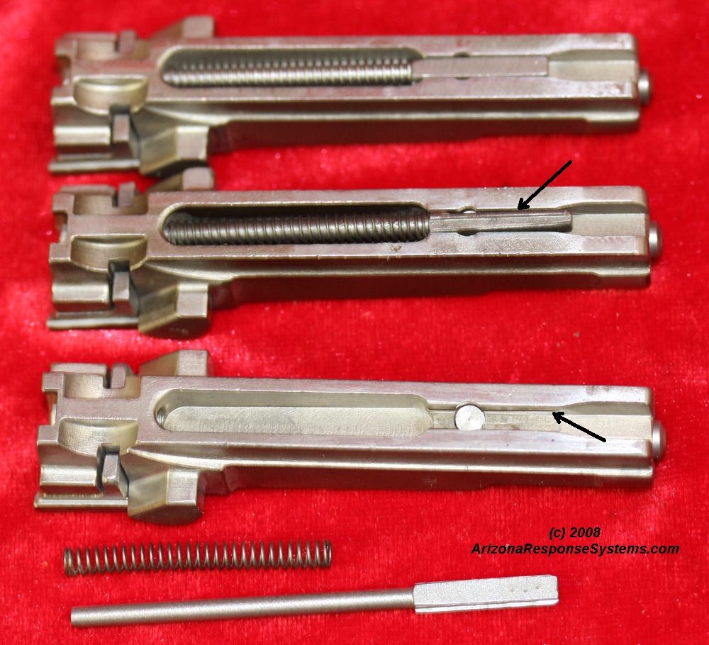
Ejector. The ejector prevents the firing pin retaining pin from falling out. he ejector has a flange on both sides that engage a keyway in the bolt. Insert the ejector into the ejector spring (bottom). Insert the ejector into the bolt body with the flange perpendicular to the keyway. Press the ejector forward until you can grasp it from the front of the bolt body (middle). Pull the ejector forward until it clears the channel, rotate 90 degrees so the flange is against the bolt body, and release it to slide into it’s keyway.
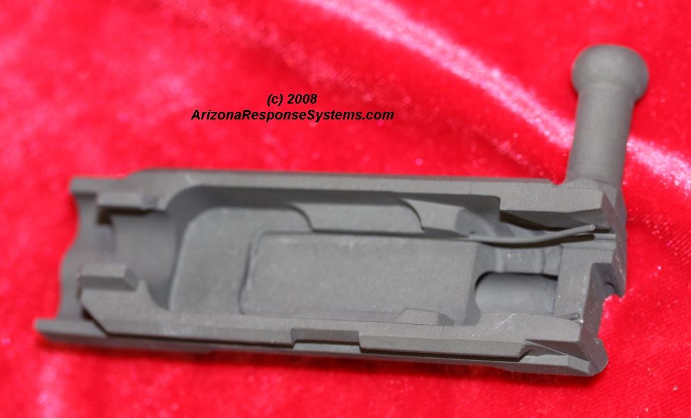
Extractor Spring. The extractor spring is a U-shaped piece of wire that snaps into a recess in the bolt carrier. The two arms press downward on either side of the extractor.
Gas System
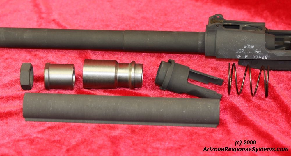
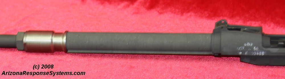
Gas System Components. The gas system is both interesting and problematic. It is interesting because it keeps the recoil energy close to the barrel, as compared to a piston above the barrel such as on the AK-47. The higher the impact of a piston, the more muzzle rise on recoil. It is problematic because it requires a 22mm and a 23mm wrench for disassembly, which makes field cleaning difficult. Combined with the corrosive primers found on the Czech 7.62×45 ammunition, specimens today often have corrosion on the outside of the barrel under the actuator.
The gas system consists of the actuator (gas-capture cup), actuator lock nut, gas cylinder, driving spring, driving spring plunger, and connector. The system may be disassembled for cleaning, but may not be removed from the barrel without removing the front sight assembly.
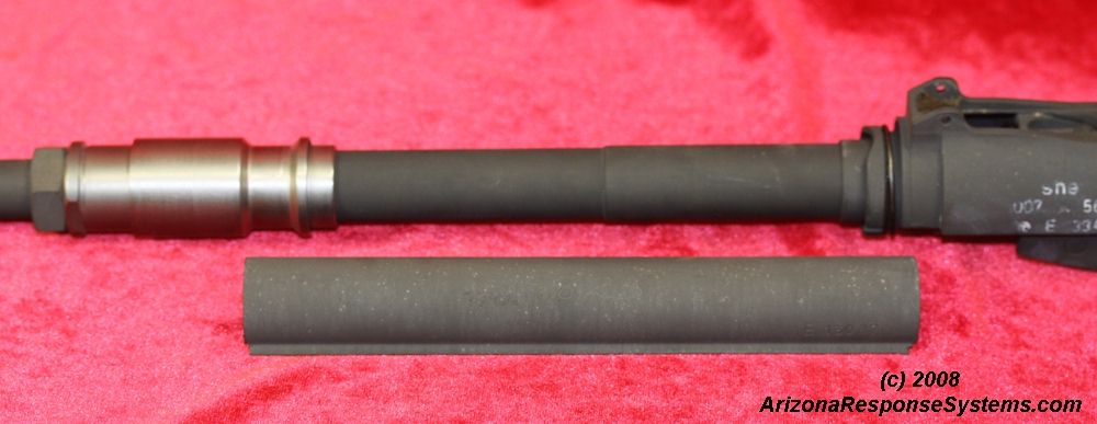
Gas System Assembly. Slide the drive spring down the barrel into it’s recess on the receiver. Follow with the drive spring plunger, aligned so it’s two arms will fit into the receiver . Follow with the gas piston, small end toward receiver. Thread the actuator onto the barrel slightly past the point where there will be room for the actuator lock nut. Thread the lock nut onto the barrel until it is aligned with the first barrel thread. Unscrew the actuator until it stops against the lock nut. The lock nut uses a 22mm wrench, the actuator a 23mm wrench. Not having a torque-specification, the best recommendation I can make is “snug.”
Connector. The connector transfers the piston energy to the drive spring plunger and causes the bolt carrier to cycle. Slip the connector over the drive spring plunger, slightly depressing the drive spring, and then slip the other end into the piston recess.
Stock Group
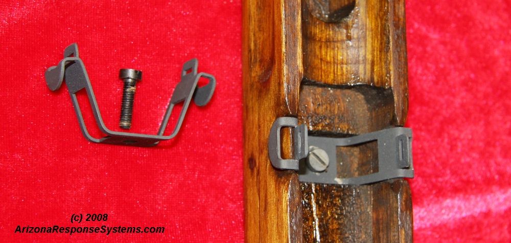
Handguard Clip. The handguard clip assembly includes the handguard clip, the handguard clip screw, and the handguard clip escutcheon (threaded insert). The handguard clip is a double-armed piece of spring steel that latches the back of the handguard. Squeezing the two arms inward releases the handguard. The handguard clip is secured in it’s stock recess by a machine screw, that threads into an escutcheon in the stock. This escutcheon should not be removed.
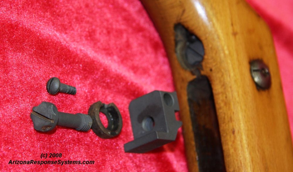
Recoil Lug. The recoil lug assembly consists of the recoil lug, the recoil lug escutcheon, recoil lug screw, and recoil lug screw lock screw. Earlier models did not have the escutcheon or the stock cross-bolt-. These were added to reduce stock cracking at the wrist. The recoil lug stops the bolt rearward movement, and acts as a camming surface (like the M1 Carbine) for securing the barreled action into the stock.
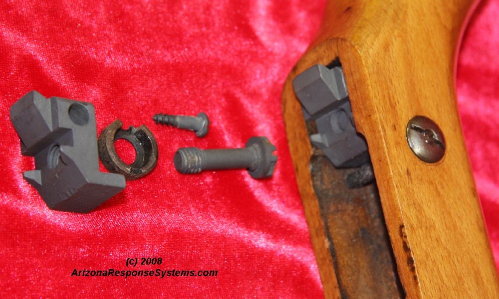
Recoil Lug Installation. Insert the recoil lug from the top, and the escutcheon from the bottom. Insert and tighten the recoil lug screw. Insert the recoil lug screw lock screw.
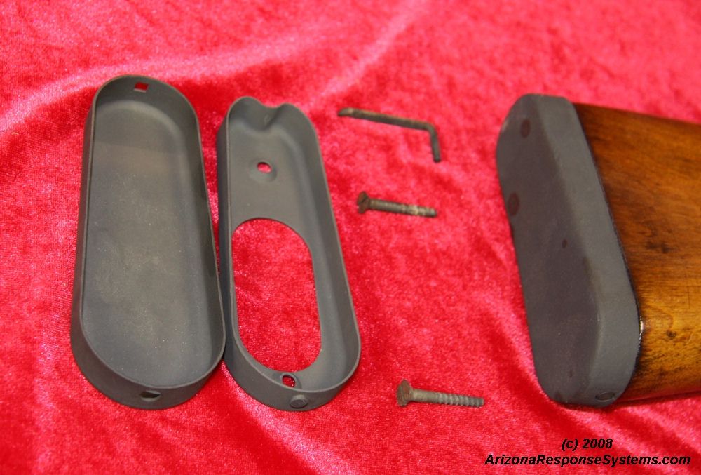
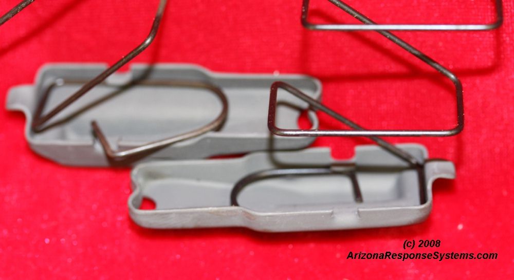
Buttplate Assembly. The buttplate assembly on later rifles consists of an inner buttplate, buttplate latch/spring, two wood screws, and an outer buttplate. The outer buttplate secures by a stud on the bottom of the inner buttplate and the leaf-spring on the top.
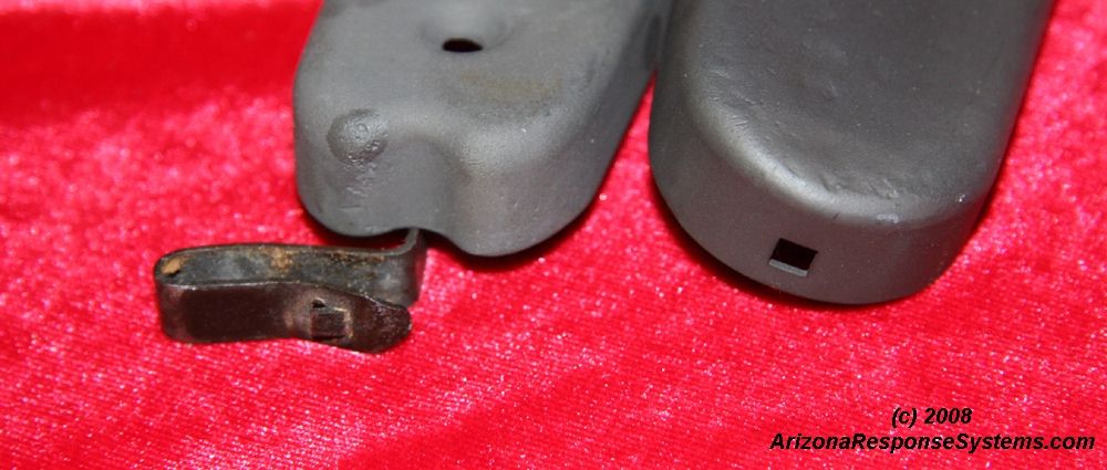
buttplate Spring The original buttplate latch was frequently broken, with one end remaining stuck in the stock. An updated S-shaped latch/spring was designed, requiring only a slight widening of the recess in the stock. This spring also broke with some frequency, but was easily replaced. It secures under the inner buttplate.
buttplate Spring. Updated buttplate latch/spring installed.
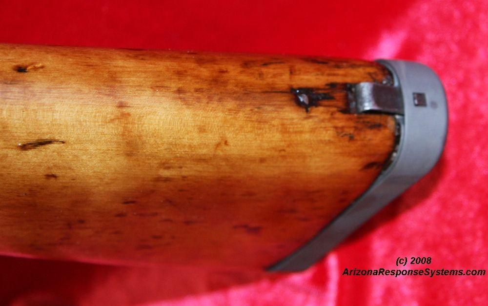
Early Stock. Early stocks were made of walnut instead of Elm (?) and lacked the cross-bolt- and the recoil lug escutcheon.
Early Stock. Another view of an early stock.
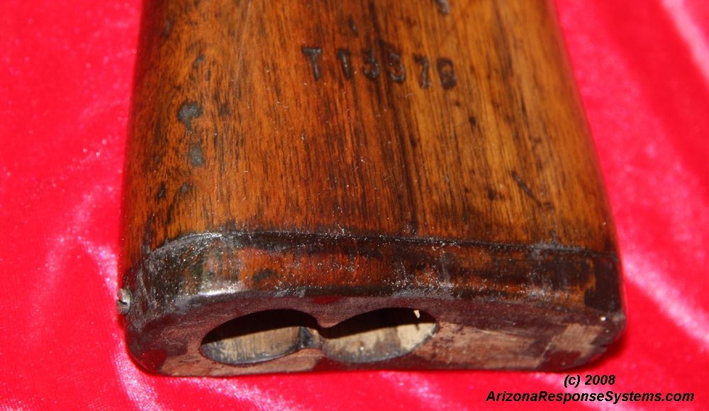
Early buttplate. Early stocks also lacked the inner buttplate and had a small wood screw as a stud to secure the bottom of the buttplate.
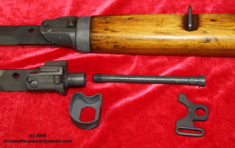
Stock Front Assembly. The front stock assembly consists of the bayonet assembly, front stock ferrule, front sling mount, and bayonet retaining bolt. Assembly is straightforward.
Misc Vz-52 Images

SHE Arsenal 007-56.# E 33488. One of the 7 rifles I rebuilt. Dark bore from corrosive ammunition, metal reParkerized, wood stripped, cracks repaired and refinished. Complete with all parts and one magazine. This has a nice stock with no repairs at the wrist. Interesting fiddle pattern to the wood. Broken buttplate retaining leafspring updated with newer style S-type leaf spring.

SHE Arsenal 007-55. # K 66948. One of the 7 rifles I rebuilt. Dark bore from corrosive ammunition, metal reParkerized, wood stripped and refinished. Complete with all parts and one magazine. Broken buttplate retaining leaf-spring. This has a very nice stock with no repairs at the wrist. Small repaired crack in upper handguard.
Further Reference

The Buddy Hinton Collection An excellent photographic reference on the 7.62×45 Vz52 and the 7.62×39 Vz52/57, including manuals, ammunition types, and accessories can be found in The Buddy Hinton Collection

Wikipedia A general overview with additional resources can be found at the Wikipedia Vz52 entry.


Leave a Reply
You must be logged in to post a comment.