AK Tutorial: Adjusting the TAPCO G2 AK Trigger
Since the Arsenal fire-control group is significantly more expensive than the TAPCO, I decided to determine if I could modify the TAPCO G2 to work reliably, safely, and consistently in the NoDak Spud NDS3 receiver.
In some circumstances, with someNDS receivers and someTAPCO G2 fire-control groups, with the trigger pulled in a certain way, the hammer can follow.
It is caused by a stacking of the following tolerances.
- receiver rail height
- bolt carrier base
- hammer-trigger hole spacing
- hammer-trigger hole height
- hammer & trigger hole distance from receiver rail
- hammer shelf dimension
- disconnector claw dimension
- disconnector travel dimension
Examining import fire-control groups show some with signs of factory adjustment and numbering to the gun. This indicates fire-control groups are not always interchangeable between guns.
One shooter’s trigger manipulation may not result in hammer-follow, while another shooter can get hammer-follow on the same rifle. A solid, fast pull to the rear will rarely get a hammer follow. A slow, smooth pull and holding at the point of hammer release may get a hammer follow.
- I identified the potential problems.
- I created a data-base of fire-control group dimensions.
- I correlated the data to yes/no hammer follow.
- I determined the dimensions that prevented hammer follow
- I determined the adjustments necessary
- I quantified the degree of adjustment
- I proofed my results on 50 rifles.
- I forwarded the data to Nodak Spud and TAPCO for their reference.
The results I obtained are dependent on the slot cut for the 2nd arm of the 2-claw trigger being 4.25mm. This is shorter than the left side cut side cut. If the cut is too long, the trigger can rotate too far forward. The rotating hammer may then hit the TOP of the disconnector, rather than the camming surface on its leading edge. result is disconnector failure (hammer follow). If the cut is too short, the trigger does not travel far enough to release the hammer. While other lengths will work, 4.25mm is the constant I used to isolate the hammer to disconnector dimensions.
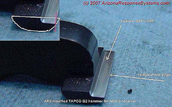
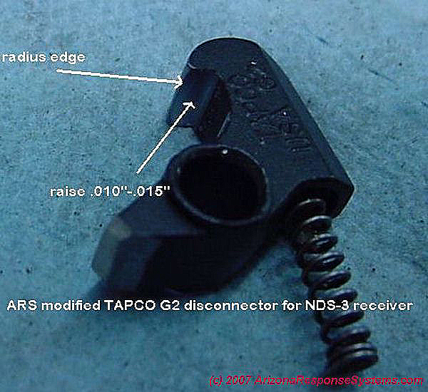
SOLUTION. Lower disconnector shelf on hammer and/or raise disconnector claw height .
DETAILS. I lower the disconnector shelf by .030″-.035″. I raise the disconnector claw height by .005″ to .010″ (total of both .040″). I lightly polish the sharp edges. Since I am machining the mold lines off and polishing the surfaces anyway, this doesn’t add much time to the assembly.
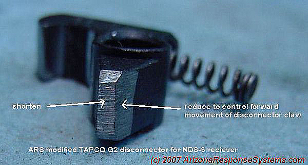
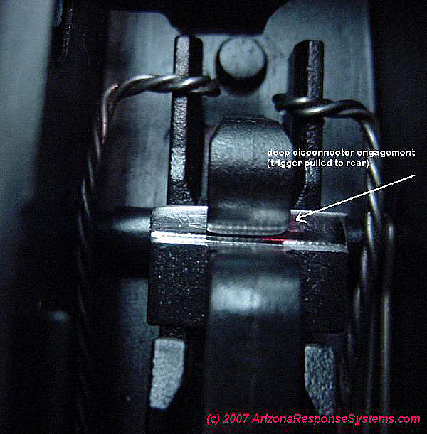
SOLUTION. Increase disconnector engagement.
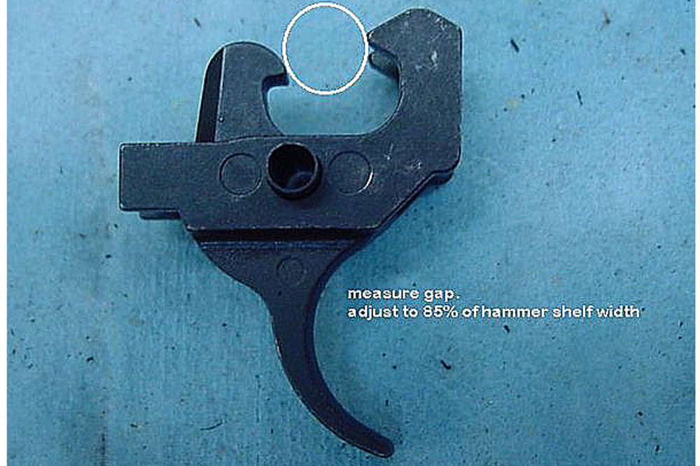
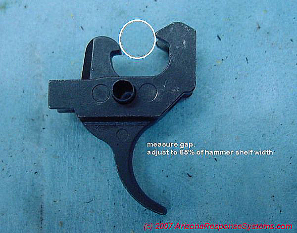
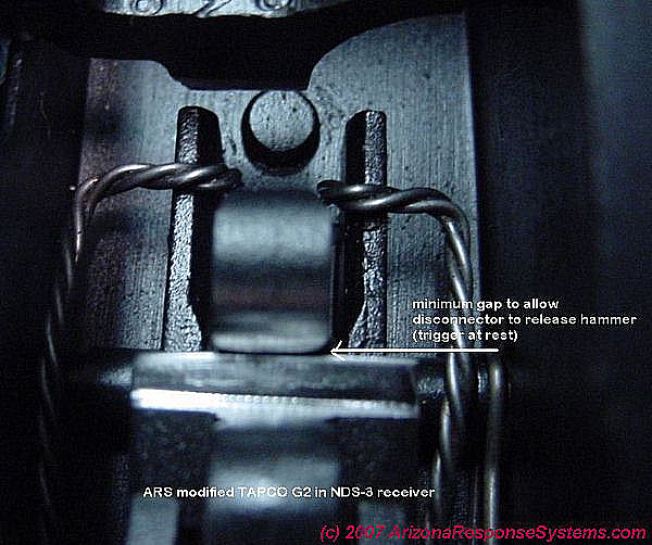
DETAILS. Cut off the front tab of the disconnector leaving .250″ from inside front of hole to end of front tab. Assemble to trigger with sleeve and spring. Measure distance between trigger claws and disconnector claw (I use a pin gauge). remove material from front underside of disconnector a little at a time until the gap on the assembled unit closes to 15% smaller than the hammer shelf width. This is usually around .350″ (.350 = 14.6% less .410″). Test with trigger at rest. rotate hammer rearward. hammer must pass disconnector in both directions without touching, but with gap as close to 0 as possible.
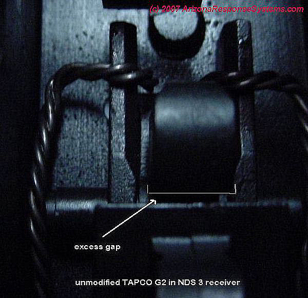
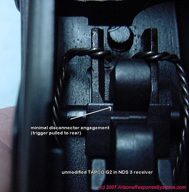
SOLUTION. Decrease disconnector engagement
DETAILS. Using the 85% guide, the disconnector gap ranged from the slightest contact to .005″. If disconnector touches hammer, polish rear of hammer and/or front of disconnector. The lateral play in the hammer makes this dimension hard to measure.
SOLUTION Adjust angle of disconnector relative to hammer shelf.
DETAILS The disconnector claw is too sharp. it is pointing downward like a hawk’s beak relative to the hammer shelf. Polish the hammer shelf. put a slight bevel (.020″) on the edge. Polish the front of the disconnector claw (the hooked beak part) Put a slight bevel (.020″ on the disconnector claw front edge.
- I assembled 30 trigger-disconnector groups
- I adjusted the gap to approximately .350″
- I marked their dimensions on the assemblies
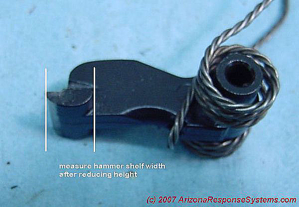
- I modified 30 hammer shelves to approximately .420″
- I marked the dimension on the side of the hammer
- I paired hammers with trigger-disconnector assemblies to those with 15% differences
All 30 guns yielded a disconnector gap ranging from slight contact to .008″ Most were 0 to .005″. a few needed the hammer shelf radiused slightly – the disconnector didn’t stop the hammer from releasing but there was slight rubbing. I have complete 60 rifles and cannot coax any of them to hammer follow. I understand that this is a small statistical sampling. I will update my results if further data collection suggests a different adjustment process.
Update. 350 trigger groups testfired with the above adjustments. Zero doubling. 2 with drag on disconnector release requiring a slight breaking of the “hawk beak” edge on disconnector.
Target trigger gap of .0.360″- .0100″
Typical hammer width after reducing shelf: 0.415″-0.005″
Leave a Reply
You must be logged in to post a comment.