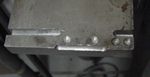
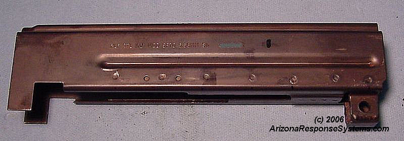
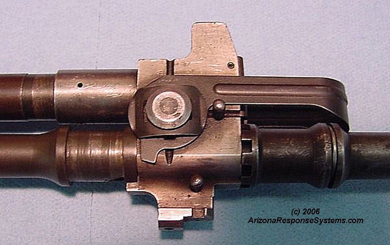
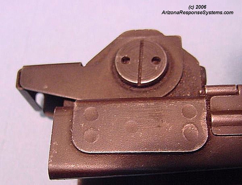
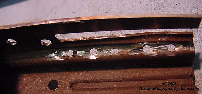
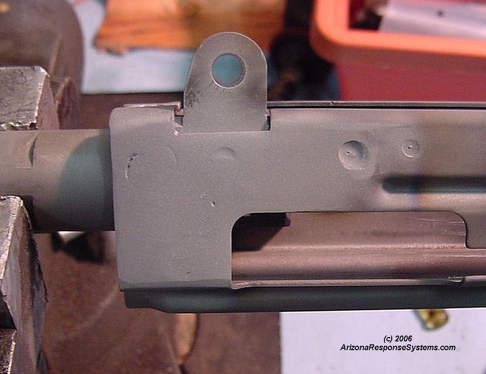
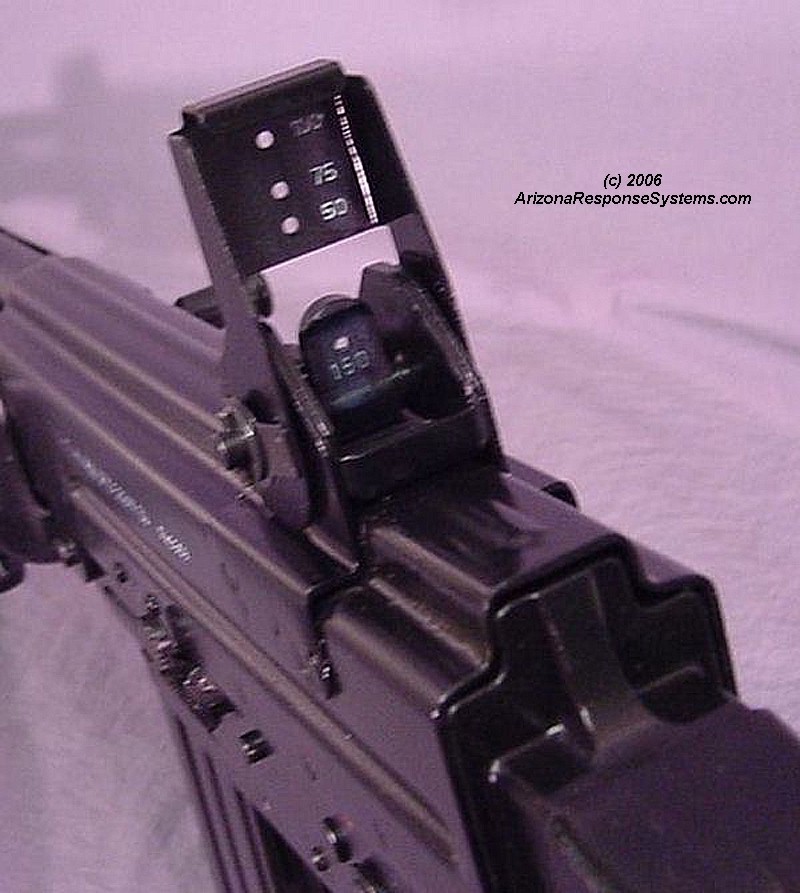
The rear grenade sight folds up for three different rifle-grenade distances. Spot welds secure the rear sight assembly to old receiver must be removed, either by drilling out (my choice) or cutting receiver from inside. There are usually 5 on each side and two on the top. Disassemble the rear sight assembly from the base.
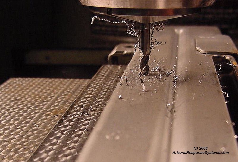
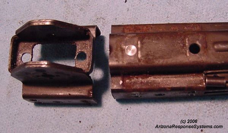
I removed the rear sight assembly by cutting through the old welds with an endmill. Here are the two spot welds on top.
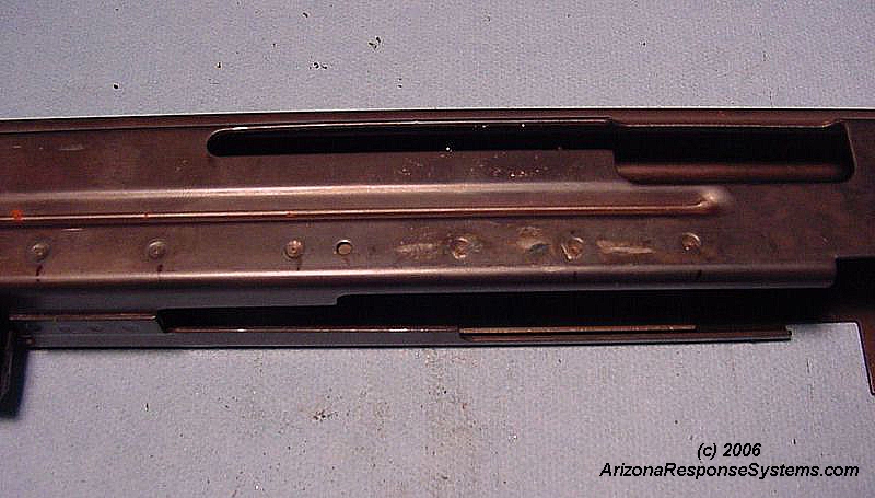
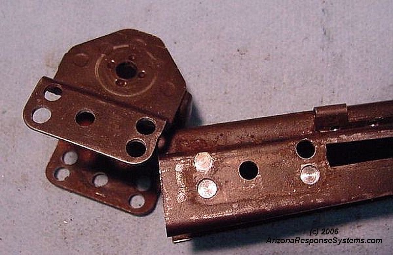
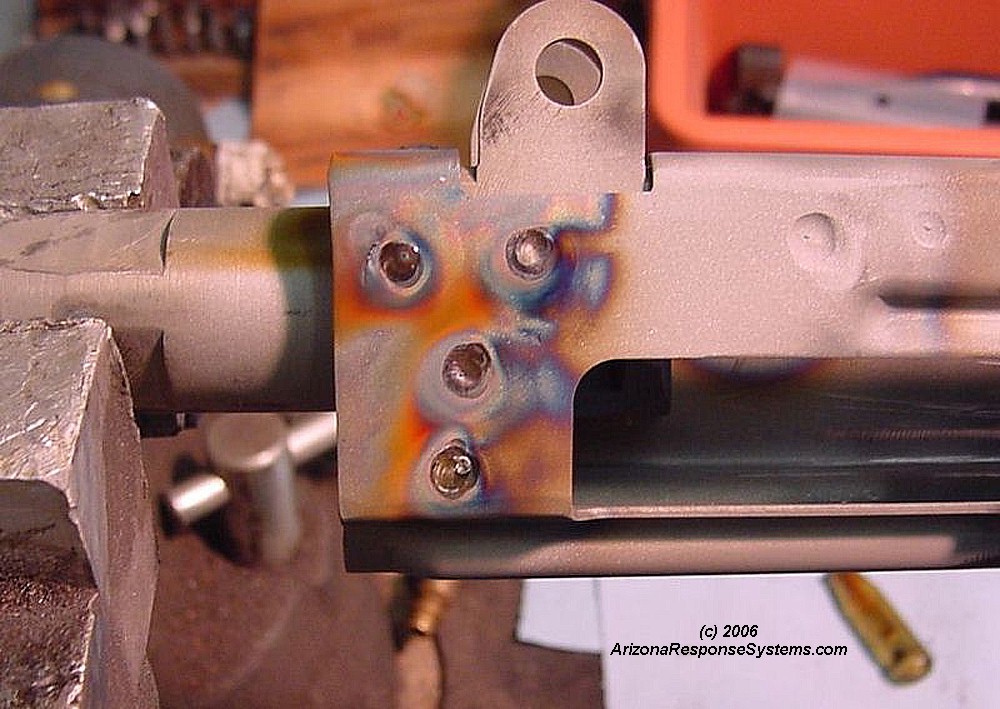
Here are the 5 spot welds on each sides.
Demil Dust Cover
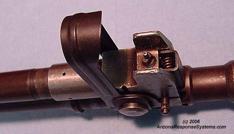
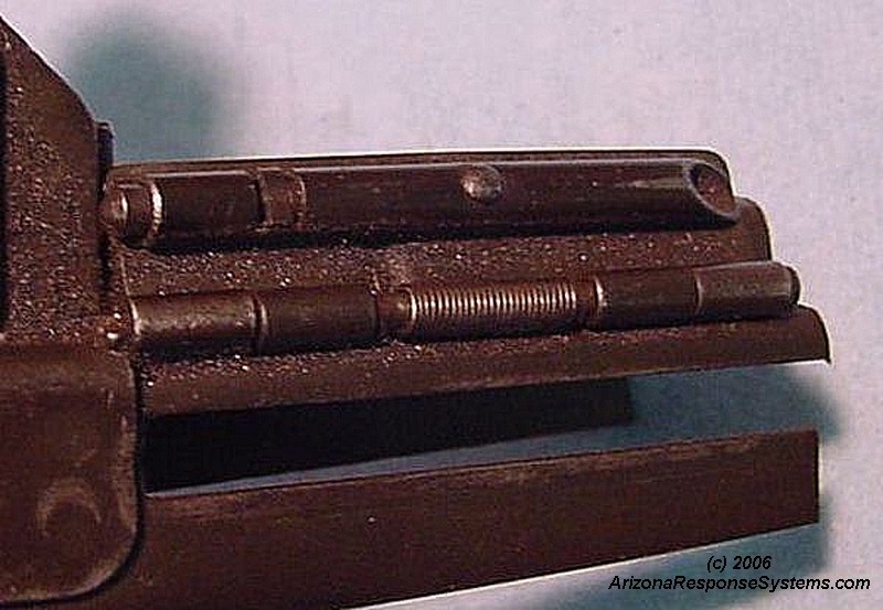
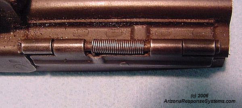
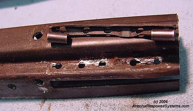
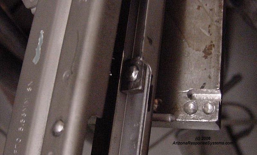
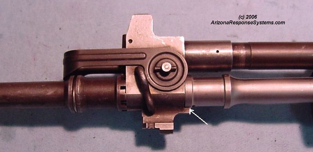
Note the operation of the dustcover and location relative to rear sight. This small piece was the most challenging part of the build. Be careful when removing the axis pin. the rear end is splayed to keep it from walking out and the tabs from the splayed end can break off easily.
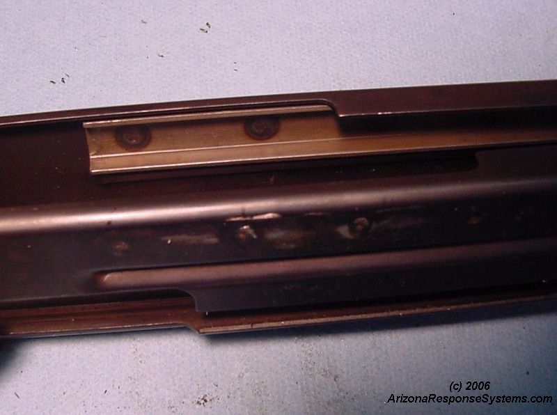
Note numerous spot welds securing dustcover to old receiver section
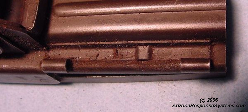
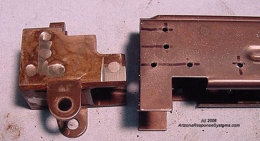
Spotwelds on dustcover, inside view.
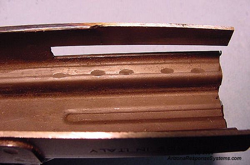
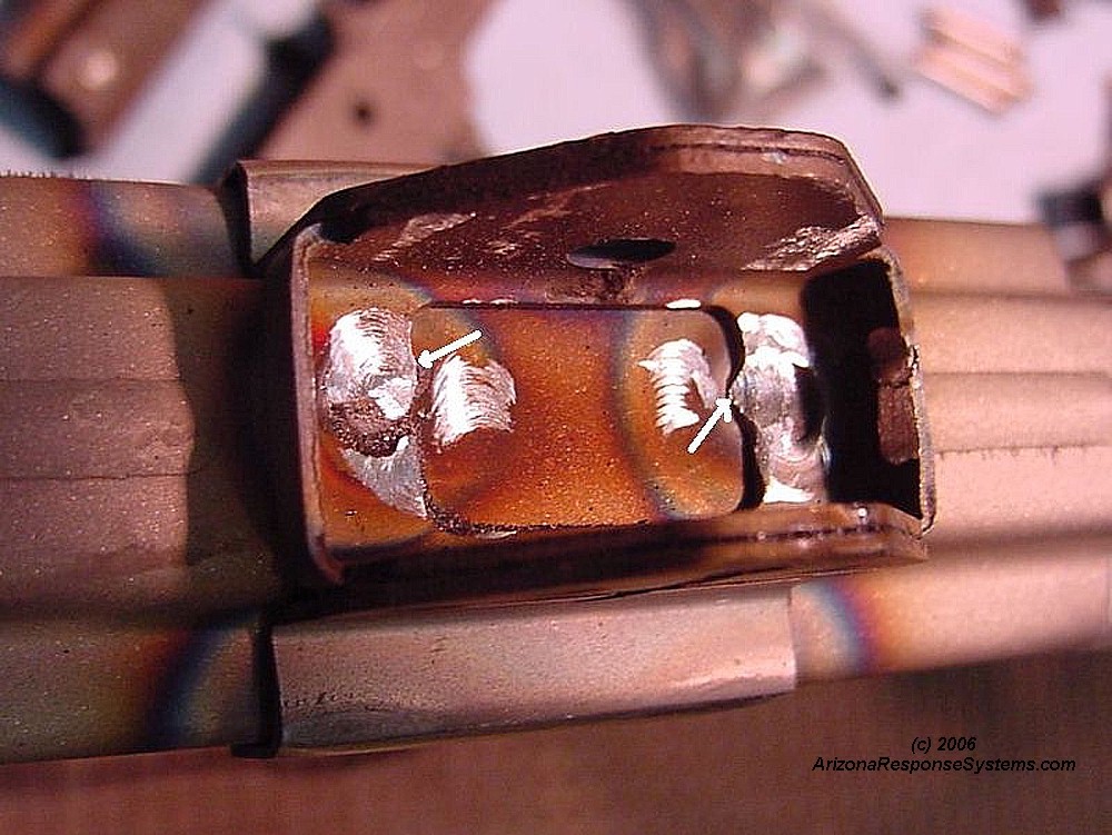
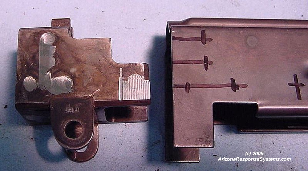
Spot welds on dustcover bracket after my first attempt to cut them out. Gentle prying with a fine screwdriver tip did not pop the bracket off – there were still bits of weld retaining the piece.
I ended up using a cut-off wheel on my Dremel tool to sever the last bits of weld. I do not recommend drilling the welds out as I did. Simply cut the welds out from the inside, using the edge of a fiber cut-off wheel. The holes that I left in the bracket made it so thin at some points that welding melted parts of the bracket.
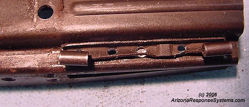
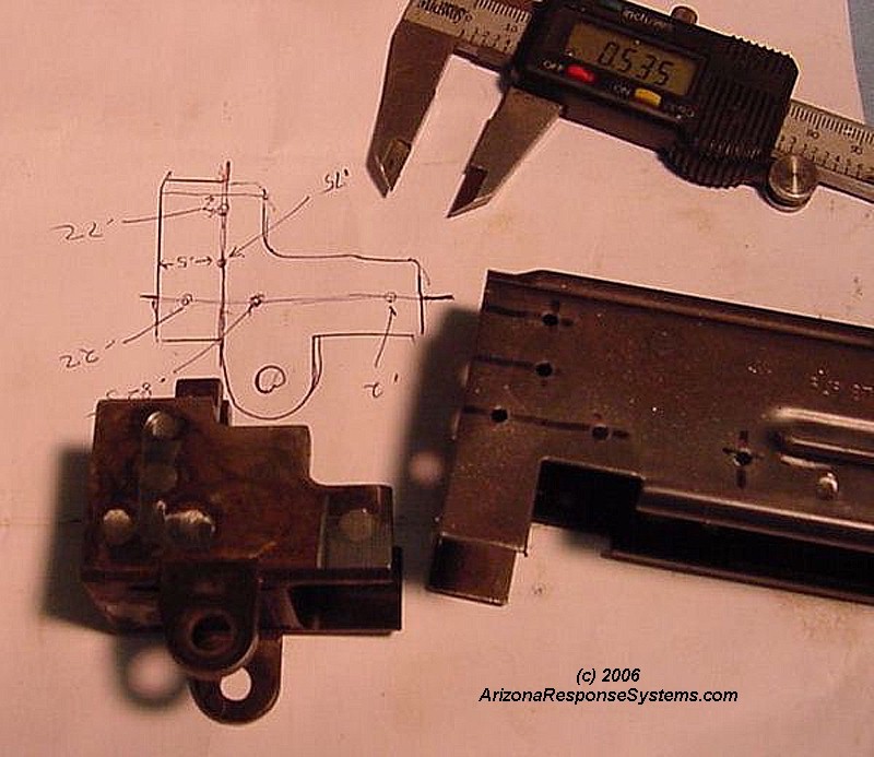
I ended up with a twisted and distorted bracket. This added considerably to assembly time as I reshaped it.
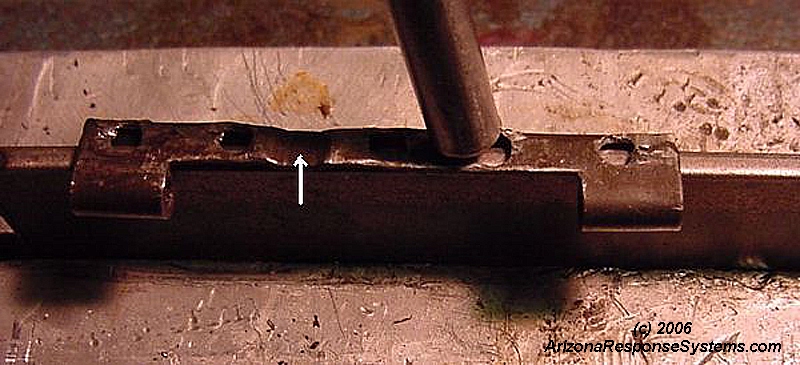
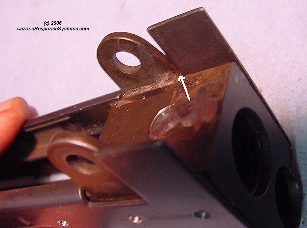
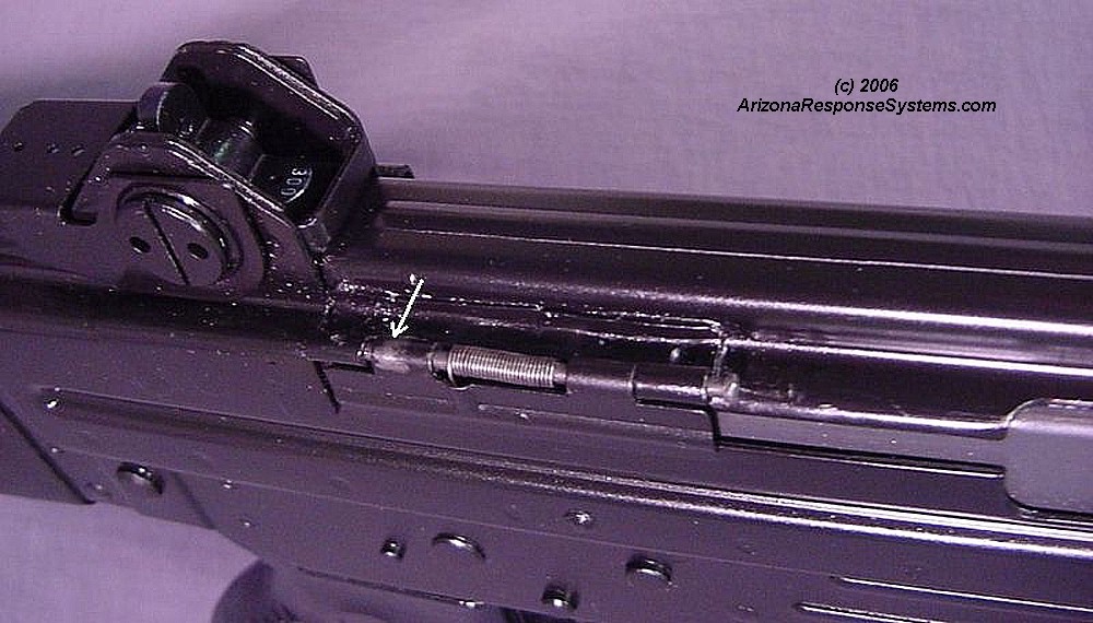
Carefully reshaping the bracket to match the receiver contour. The hump indicated by the arrow is to retain the end of the dustcover spring, and must not be flattened. Retaining this hump was one of the reasons that reshaping it was such a time-consuming effort – I couldn’t just put it in parallel clamps and squeeze it flat.
Prepare Bolt & Carrier Assembly
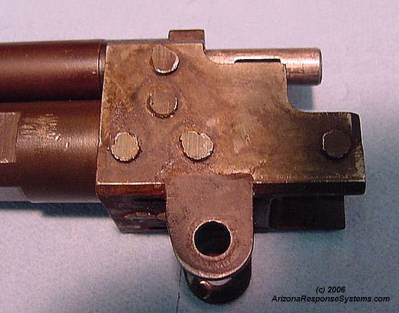
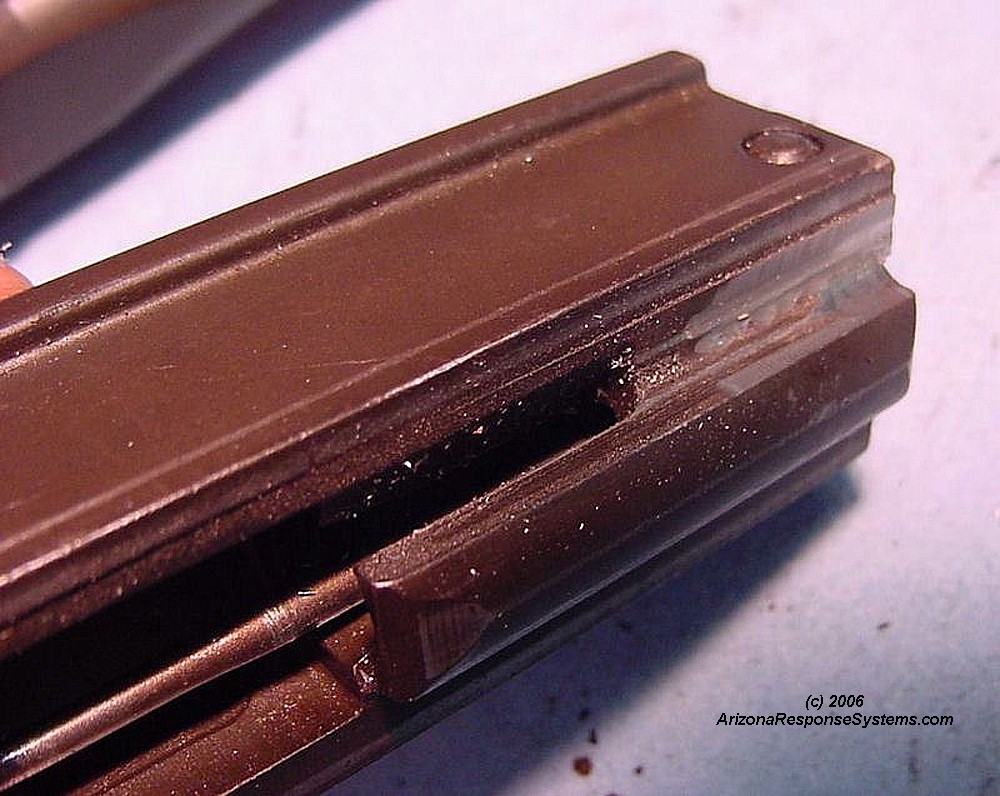
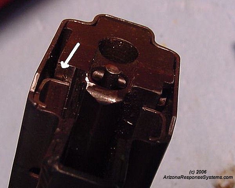
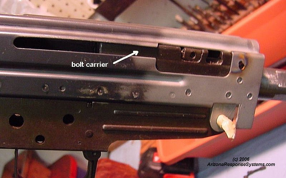
The full auto bolt carrier will not fit in the semiauto receiver. You must mill off this ledge that would trip the auto sear trip lever.
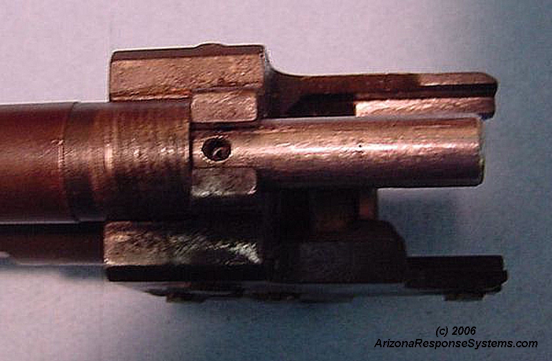
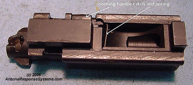
Top view of bolt and bolt carrier assembly. Remove cocking handle by sliding catch to the rear.
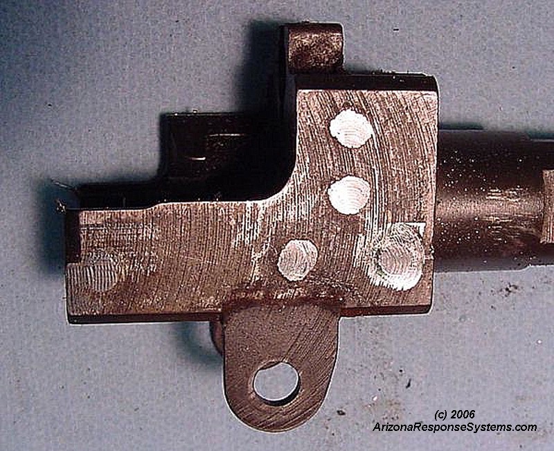
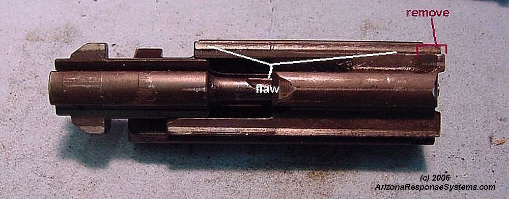
Bottom view of bolt and bolt carrier assembly, Note that the left rail is slightly flawed. The height was set by two passes with a cutter, but apparently the bolt carrier shifted or the cutting head was not perpendicular to the work area, as the front outside and back inside of the rail are higher than their adjacent areas. I recut this surface flat.
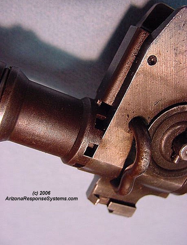
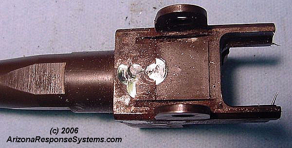
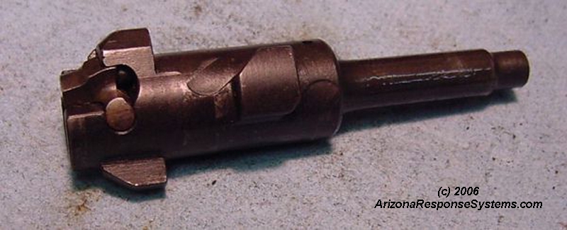
Bolt removed from bolt carrier. Firing pin remains attached to bolt carrier. The extractor was a challenge to remove. You must depress the stiff plunger and spring to clear a ledge on the inside of the extractor axle before the extractor is freed.
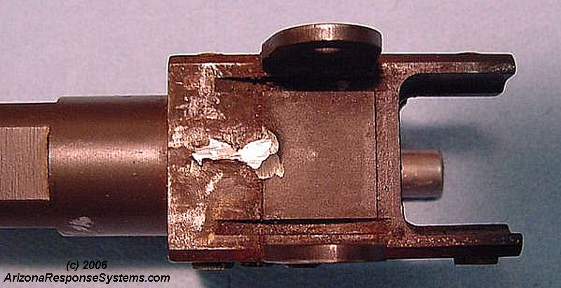
Bolt carrier after milling off the auto-trip ledge. The junction of the two surface should not be 90 degrees, a slight radius increases strength. I cut the radius with a Dremel cut-off wheel and finished with #80 sandpaper on a fine chainsaw file.
Bolt carrier will now fit in the semiauto receiver
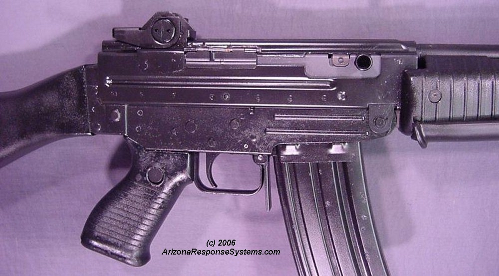
Trigger Mechanism
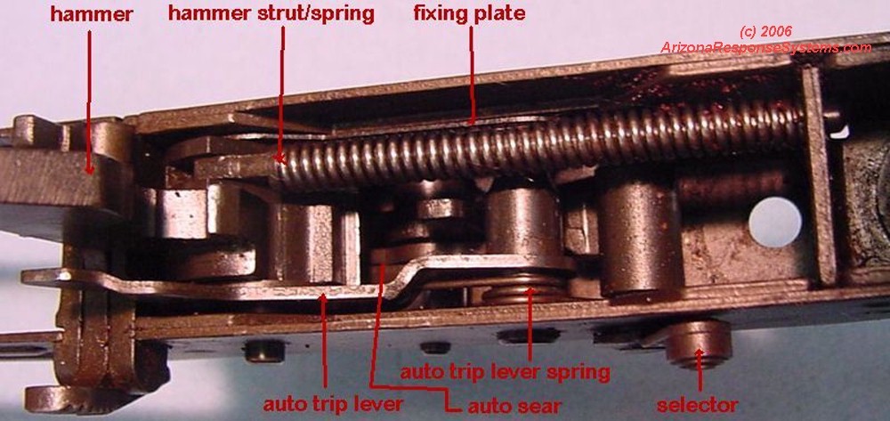
Carefully note position of trigger mechanism components.Disassemble the trigger mechanism. Rotate the selector until the cutout matches the detent spring portion of the fixing plate. Remove the selector. The holes in the fixing plate are offset from the grooves in the hammer and trigger axis pins. When the selector is installed, the fixing plate locks the trigger and hammer pins in place. With the selector removed, you can shift the plate far enough to free the hammer and trigger pins.
Note how the right side spring arm functions to lift the front of the trigger which returns the trigger forward. The left side spring activates the auto sear to catch the hammer. I cut-off the left side spring arm. The axle roll pin was rusted in place and it crumbled on removal – I replaced it with a new roll pin.
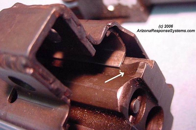
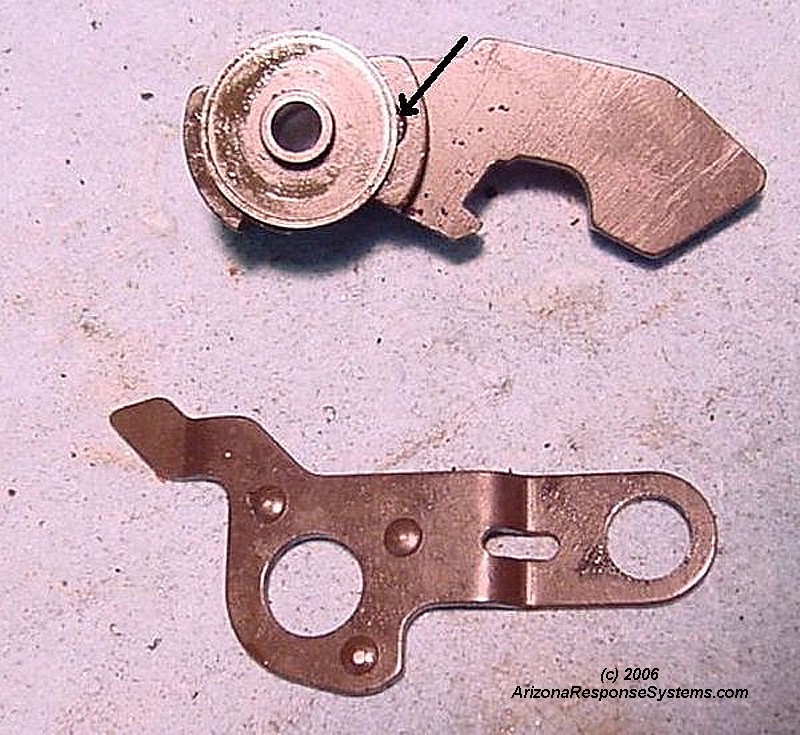
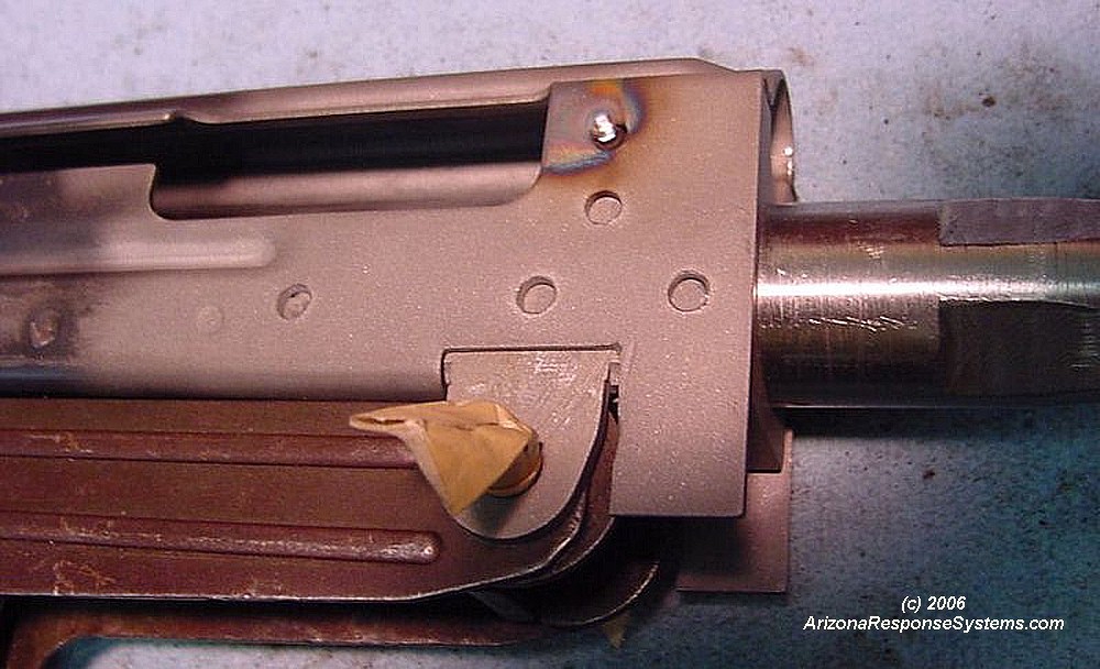
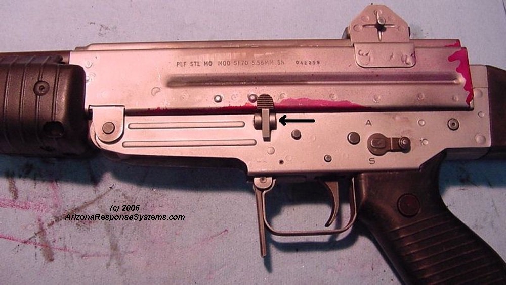
The hammer spacer disc holds the hammer strut pin in place – see arrow, The automatic sear trip lever is not used in the semiauto rifle and is replaced with a larger spacer on the hammer from the JM Tech “semiauto lock-out kit”. This larger disc fills the space previously occupied by the auto trip lever.
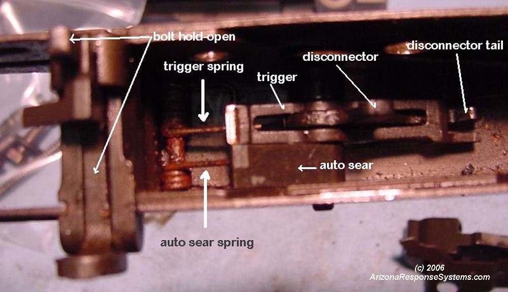
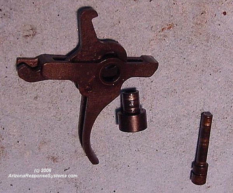
I replaced the full-auto disconnector with a US made semiauto disconnector from JM Tech. Note how the disconnector spring (not visible in picture) lifts the tail of the disconnector. While you could modify the original full auto disconnector to function in semiauto only, it is an inexpensive part to meet the 7 US parts requirement. The JM Tech semiauto lockout kit also comes with a wider trigger/disconnector axle sleeve. The wider sleeve occupies the space previously filled by the auto sear. The spacer was a tight fit so I polished it with #400 crocus cloth until it moved smoothly.
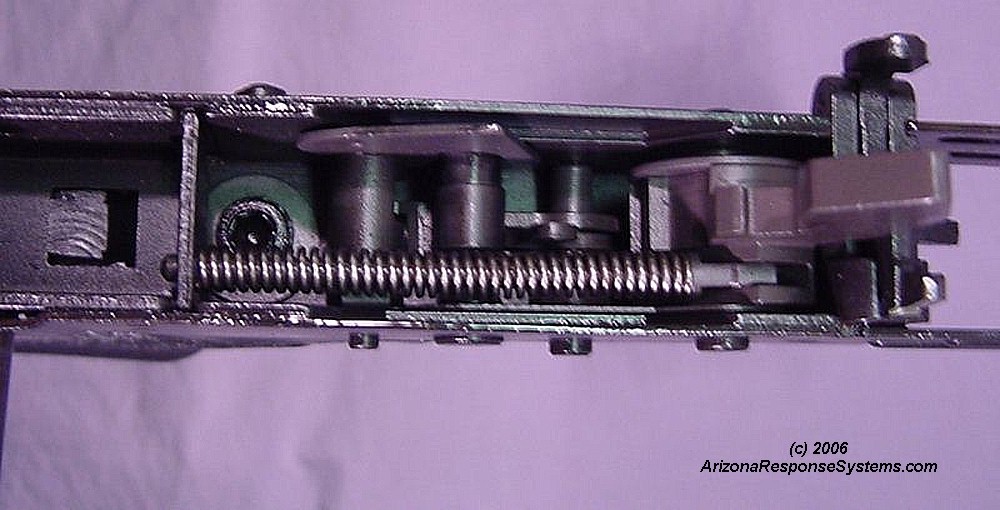
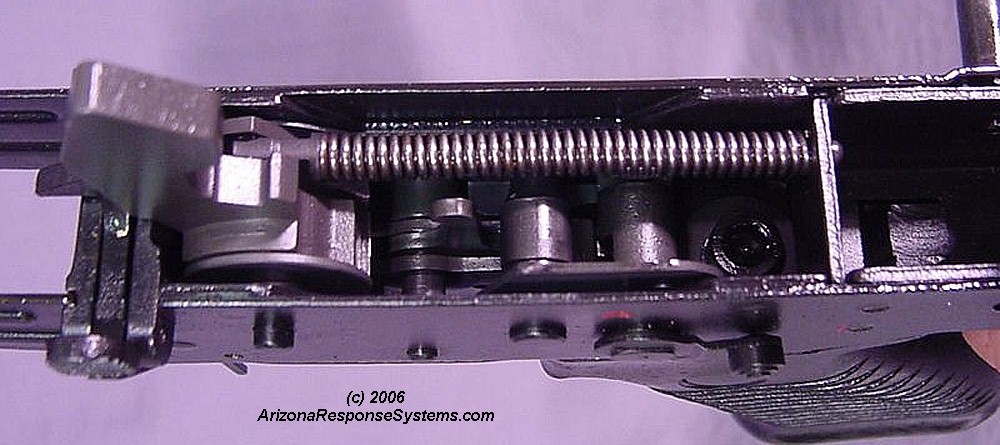
Trigger mechanism reassembled with semiautomatic parts installed.
I’m showing the reassembled mechanism to clarify the relationship of the parts. You should leave the trigger mechanism disassembled at this time to fit the trunion to the upper receiver. The JM Tech semiauto lockout kit makes the rifle fire semiauto in both the semiauto and full auto selector positions.
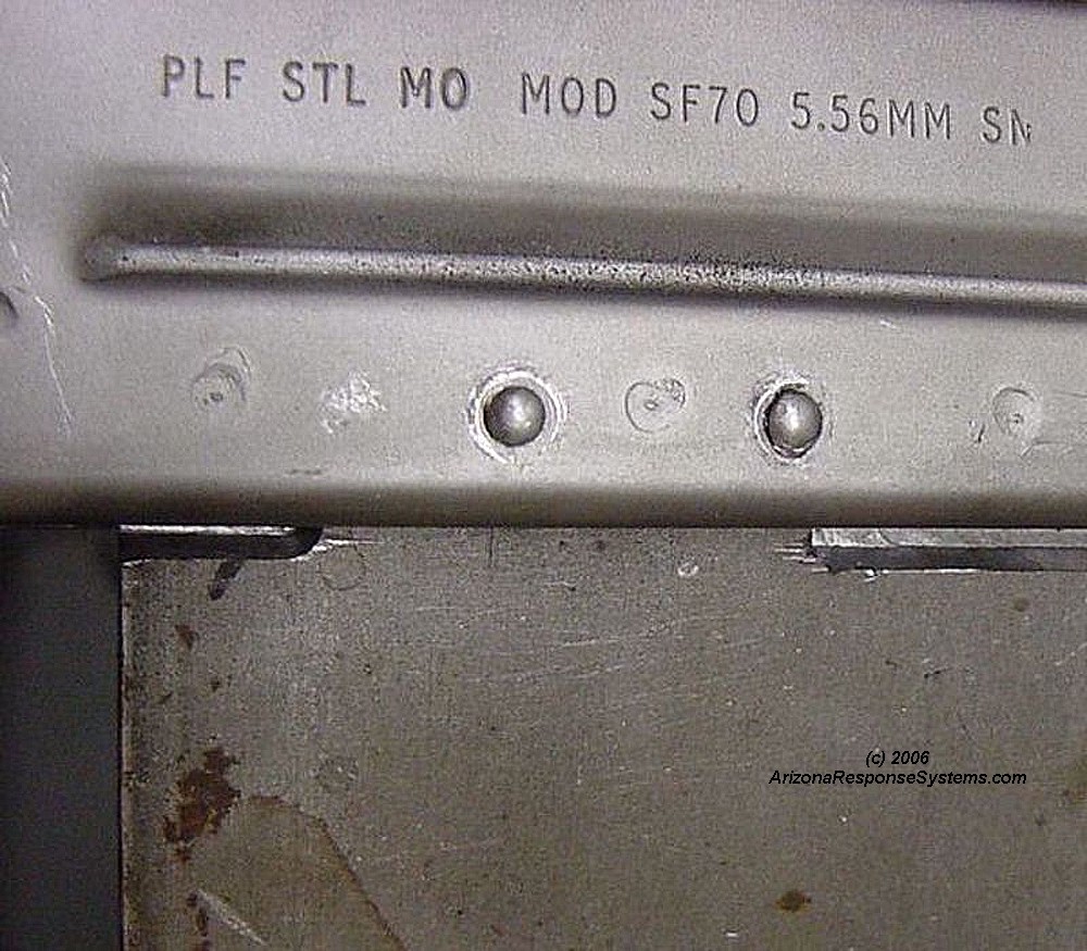
Install Rear Sight Base
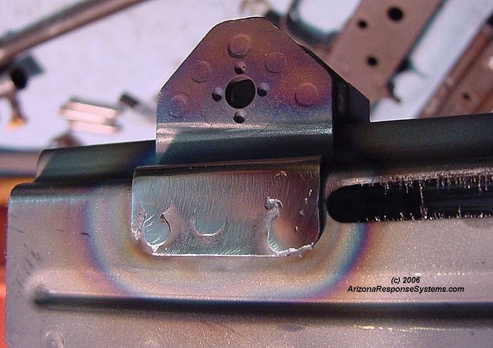
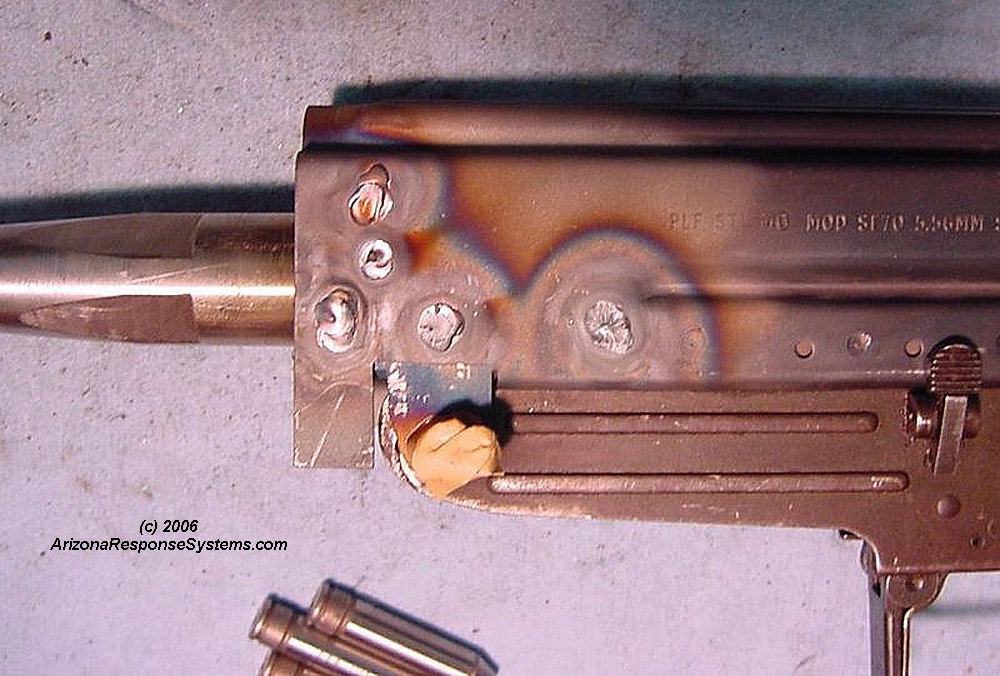
I installed the rear sight base after the trunion. It is centered between the two rib sections on the spine of the receiver. I think it would be better to install it before the trunion, as you have greater access to the inside of the receiver to clean up the welds if the trunion is not yet installed. Here I have spot welded the rear sight base on the receiver and ground the excess weld off. I later discovered I needed to remove these two protrusions for the rear sight leaf spring to fit snugly in the recess.
Clamp the rear sight gently, preferably with a copper or brass block inside to prevent crushing and to act as a heat-sink. Weld once on each side, and allow to cool, then the second spot on each side, allow to cool, etc. If you allow the receiver to get too hot, you may experience some warpage. Dress down the welds. You may also silver solder the sight base instead of welding.
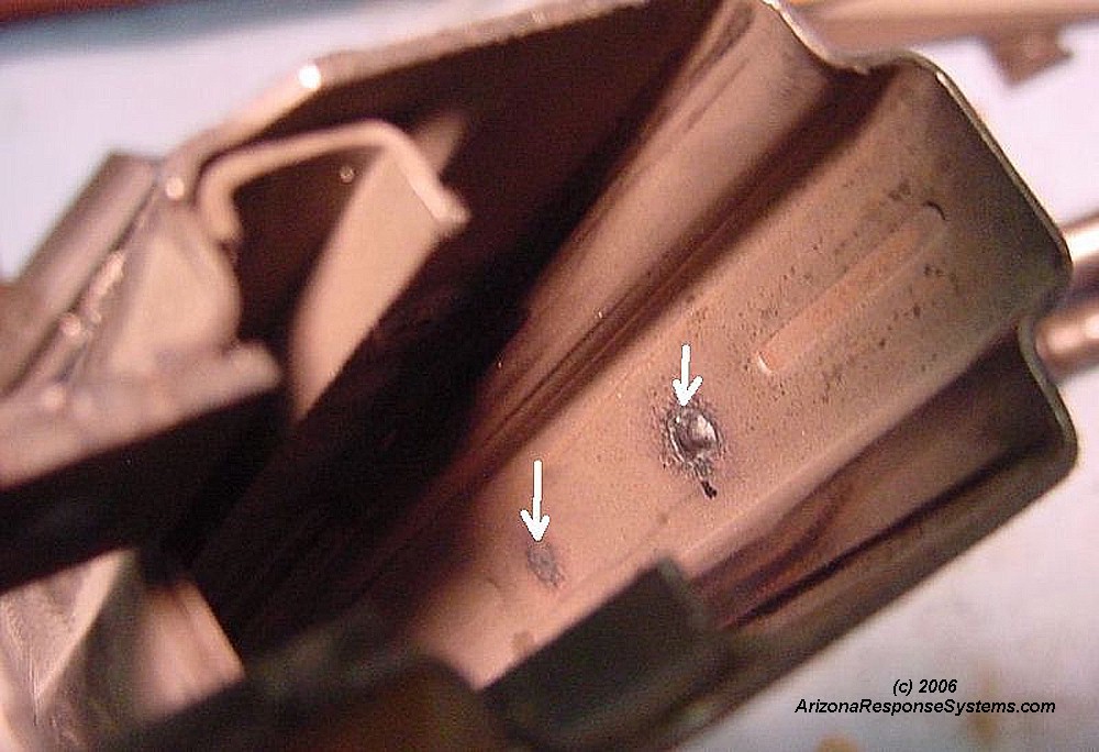
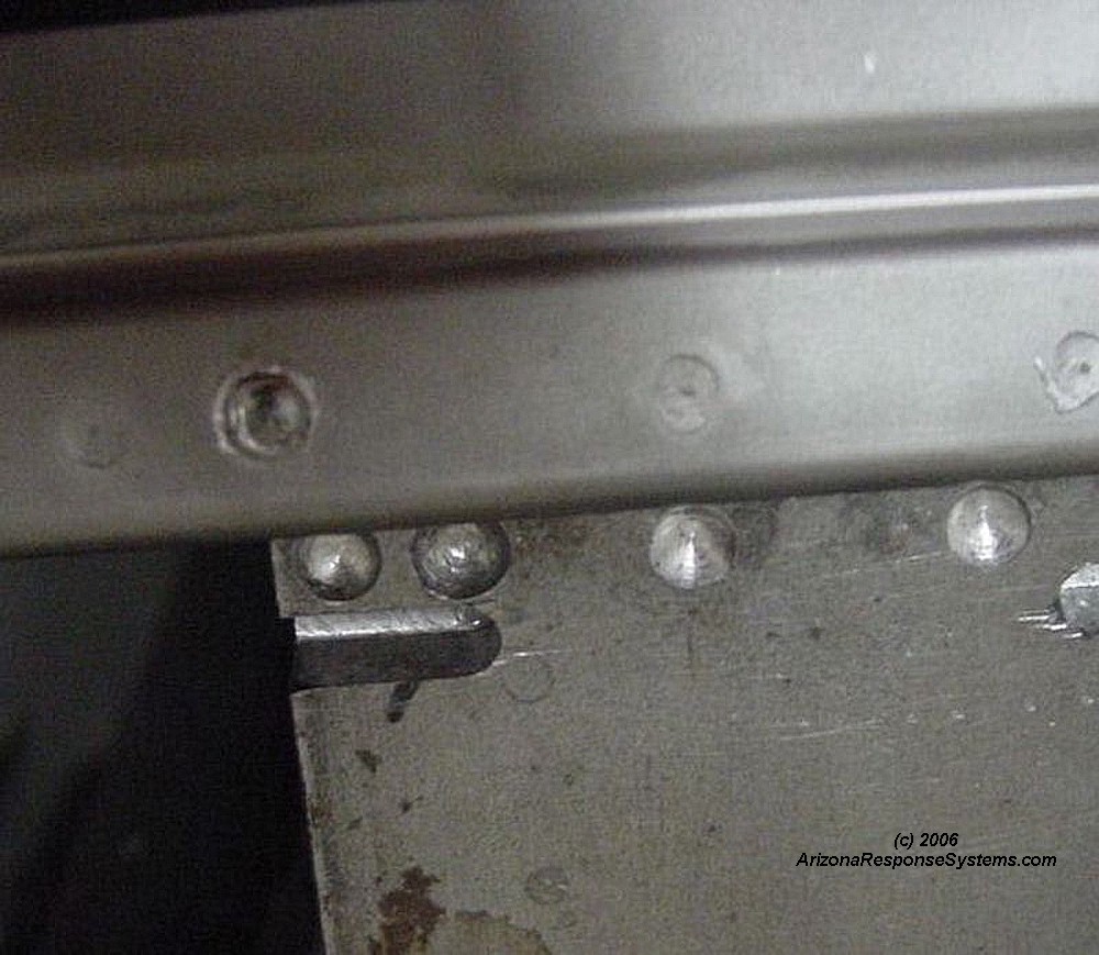
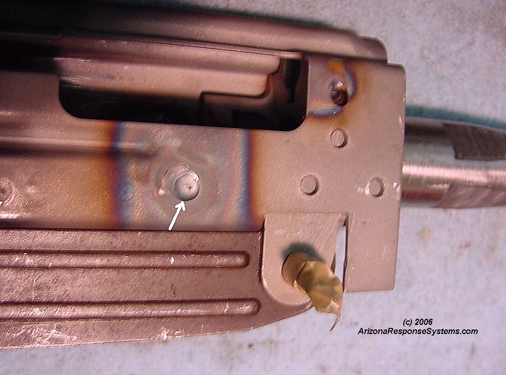
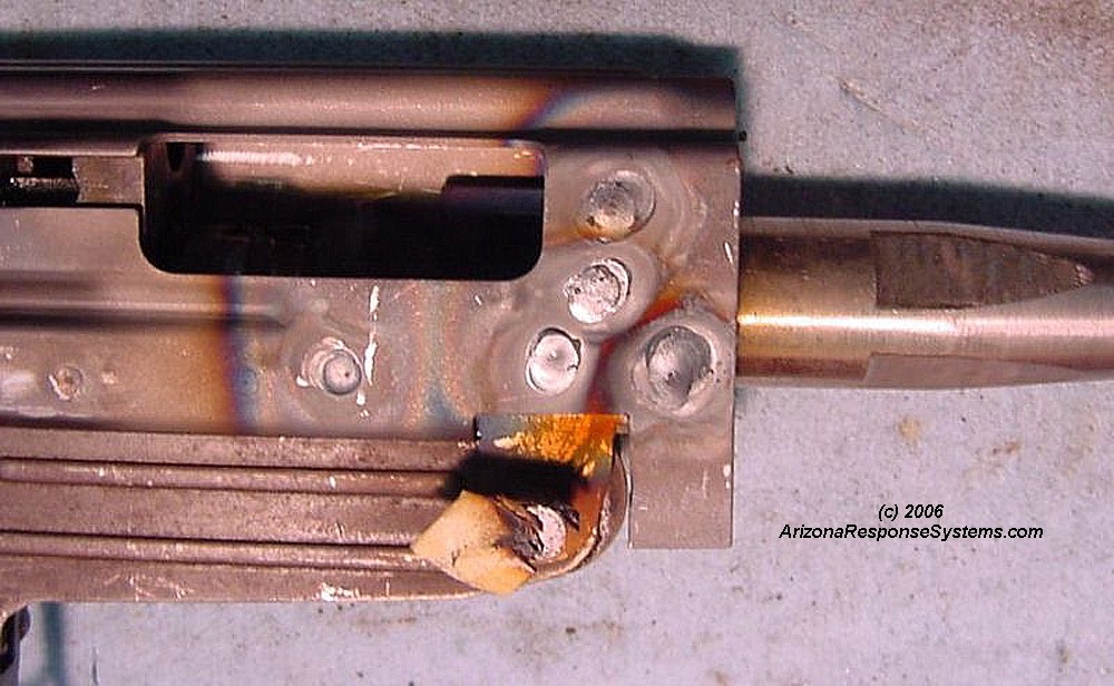
Spot-welding the top front hole was perfect, but the back hole left a small amount of slag buildup on the inside of the receiver, which must be sanded flush.
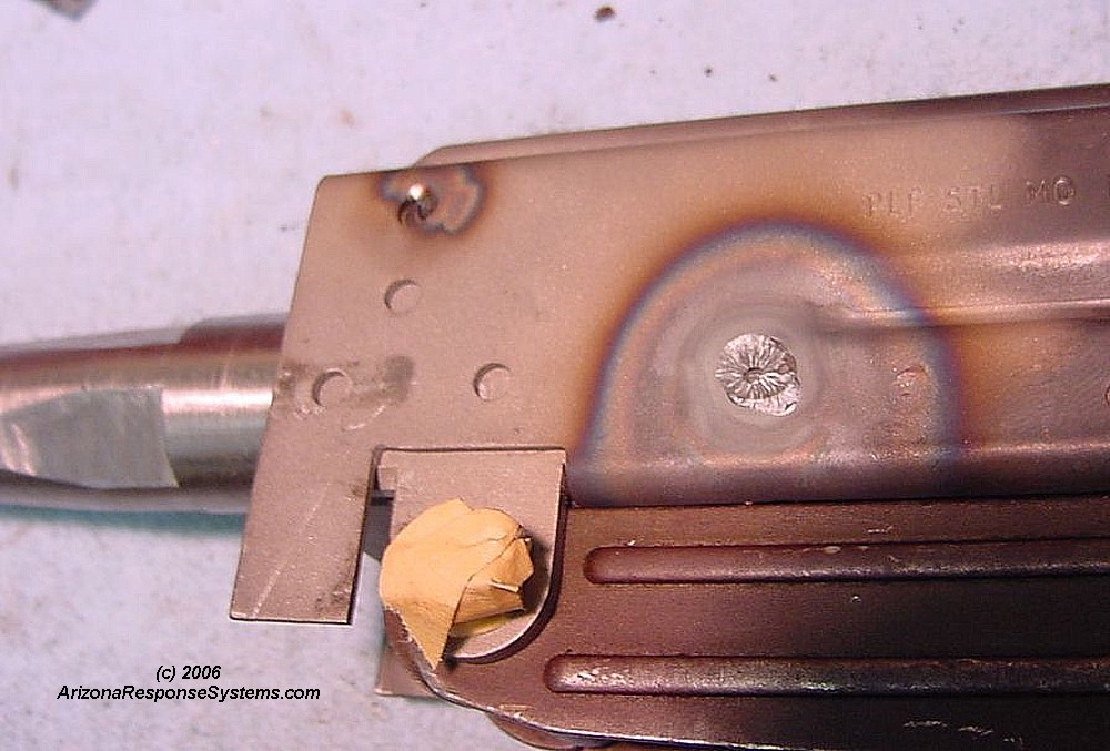
Another view of the weld bubbling through just a tiny bit. A few file strokes and then 80# sandpaper cleaned it up. It would have been a bit easier to clean up these inside welds had I not yet installed the trunion.
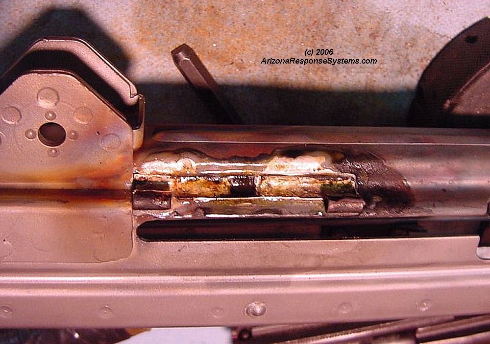
Install Dust Cover
I installed the dustcover after the trunion. I recommend installing it prior to the trunion for the same reasons given for the rear sight base. I attempted to weld this tiny bracket but melted part of it. I fabricated the missing section from shim stock and soldered it on. I recommend silver soldering as its much easier than TIG welding. You can also place a tiny TIG weld on either end of the bracket.
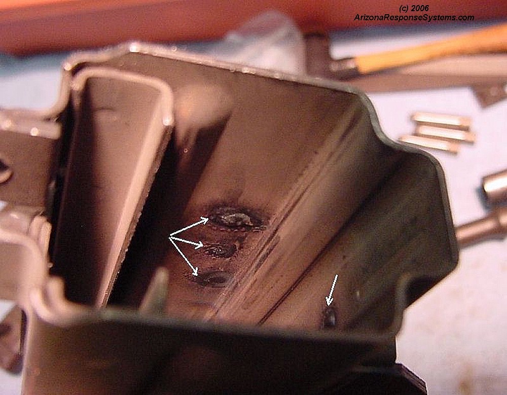
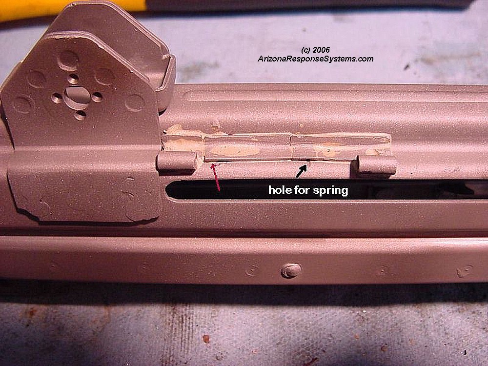
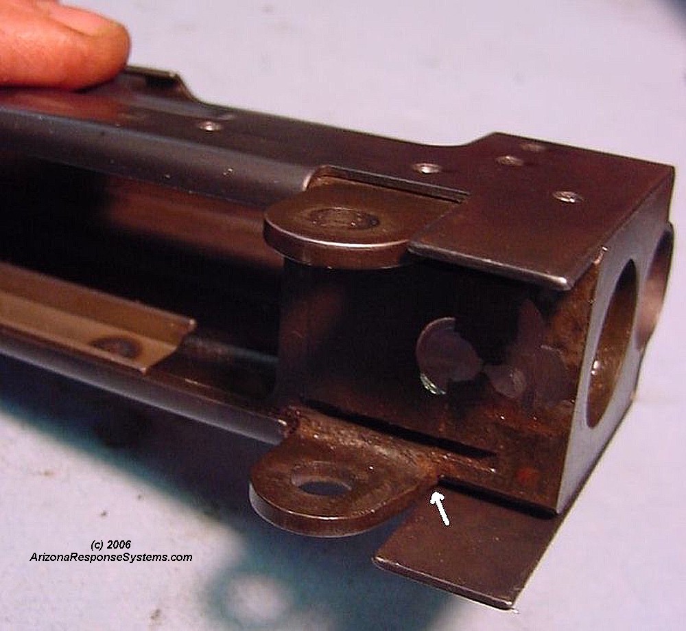
Bracket after cleaning up solder. The solder fills the holes and will look like a spot weld when finished. I had to drill a hole for the dustcover spring as the part of the bracket that would trap the leg of the spring was in the melted area. The red arrow shows a barely discernable spot where my replacement bracket section was too wide. This tiny spot put enough friction on the dustcover to prevent it from flipping open smoothly, which I only discovered after refinishing and reassembly.
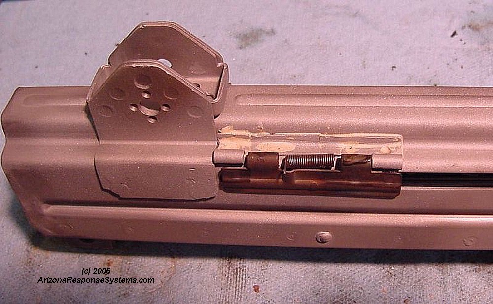
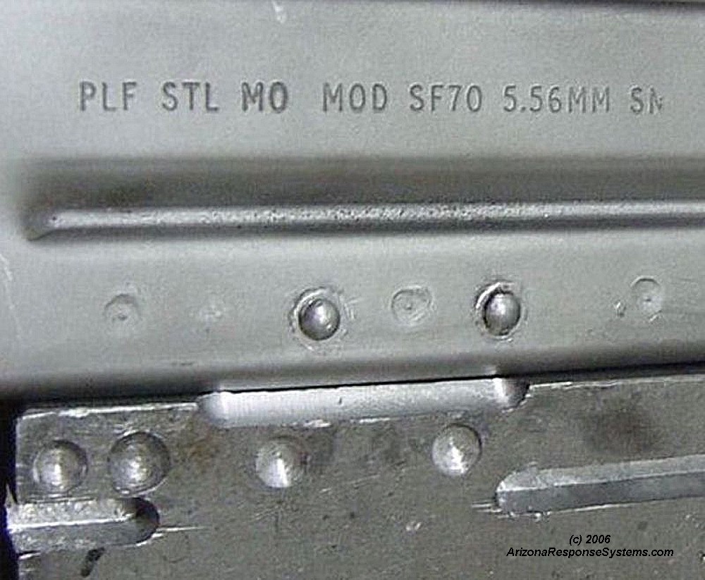
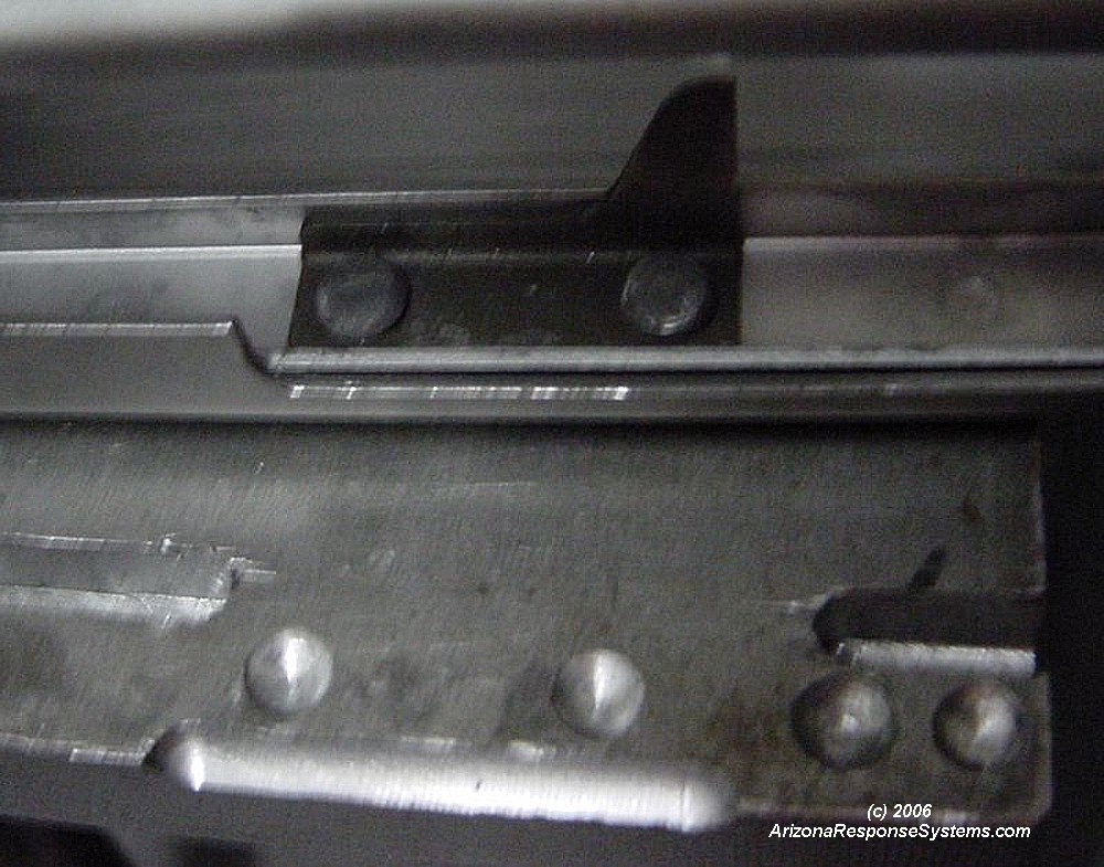
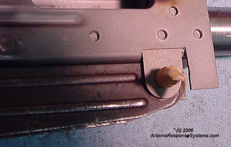
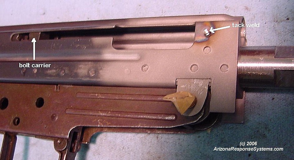
Test-fitting the dustcover. Note that the dustcover bracket does not quite touch the rear sight base. At this time, test-fit the bolt carrier again and insure it slides easily back and forth with only gravity.
Rivet Rail Support and Ejector
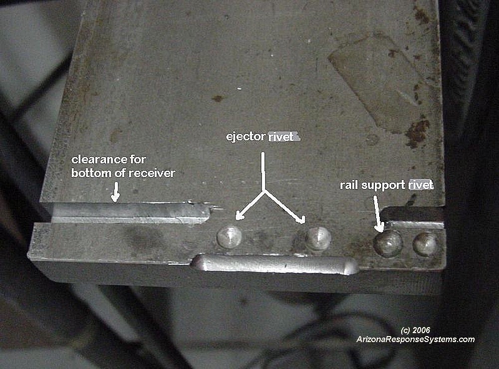
When to do this step is a tough call. I did it after installing the trunion. The advantage of installing it after trunion is that once installed, the ejector prevents effective polishing of the left rail, if that should be necessary. The advantage of installing it before the trunion, is in case you dent the receiver when expanding the rivets, it may be easier to squeeze out the dent before the trunion is installed. I recommend at least riveting the rail support before the trunion. When to do the ejector sequence is your personal preference. I fabricated a steel plate anvil to support the inside of the receiver when riveting the ejector and the rail support. On the rail support, I made two holes – a small one to better support the rivet head when I started compression, and a full sized one for after the rivet head began to flare. There are many different ways to flare the rivet head. If I were doing a number of receivers, I would have made a head for the 12 ton hydraulic press. Some have also made adaptors for large bolt cutters to flare rivet heads. On this one, I used a carbide ball endmill to machine the mirror image of the rivet head into a hardened steel punch. Dozens of moderate hammer strikes on the punch will form the rivet head better than a few heavy bashes. On the ejector side, I used the flat metal to start the rivet, then moved to the recess to finish it. The plain flat metal seemed to work better than my starter hole. It flattened the inside head of the rivet slightly which I prefer to the full round head on the original.
Ejector side on the anvil plate, with rivet installed.
Rail support rivet installed
Alignment of plate anvil to rivets
Ejector rivets, inside view.
Rail support rivet, inside view
Prepare Trunion
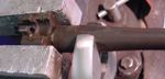
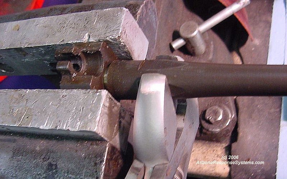
Removing the old barrel from the trunion. If you are reusing the old barrel, there is no reason to remove it. Even if you will be using a different barrel, leaving the old barrel in the trunion for now will make aligning the trunion to the receiver easier. I removed the old barrel from the trunion first because I was not sure how tight it was going to be. I was concerned that a super-tight barrel removed after the trunion was installed would leave clamping marks on the sheet-metal receiver. My concerns were unfounded as the barrel unscrewed easily with approximately 65 foot pounds of torque.
At this step I had already installed the new JM Tech barrel (1-9 twist, six groove, made by Wilson). You will still have the original barrel in place. Do not remove the old barrel until you have welded the trunion. Follow the trunion prep and welding steps as if the old barrel were still in place. The JM Tech barrel comes with a shoulder deliberately oversize by approximately 0.020″. This allows you to set the headspace without purchasing an expensive ($100+) chamber reamer.
I lathe-turned the shoulder until the bolt would just barely close on a Clymer .223 Remington NOGO gauge with the barrel hand tight. I figured with the relatively coarse thread pitch on the barrel, when I torqued the barrel on, it would close the headspace an additional .002″-.003″ which would result in a tight close on a .223 Rem GO gauge. Jeff at JM Tech recommended a tight headspace and I’ve also found a tight close on my .223 Rem gauge will be fine with a 5.56mm NATO cartridge. What I didn’t expect was for the barrel shoulder to be a bit softer than a FAL barrel have a greater crush factor than the 15 degrees I had planned on. When I had torqued the barrel to approximately 60-65 foot pounds, my headspace had closed to the point where the bolt would not lock on my .223 Rem GO gauge. I used a punch to indicate how far I had turned the barrel, then removed the barrel and cut the chamber .001″-.002″ deeper. When I reinstalled it, it closed nicely on my GO gauge.
Locating the holes on the new receiver.
The two upper holes align vertically, while the bottom three align horizontally. It may be easier to trace the trunion, and make a template to transfer the holes
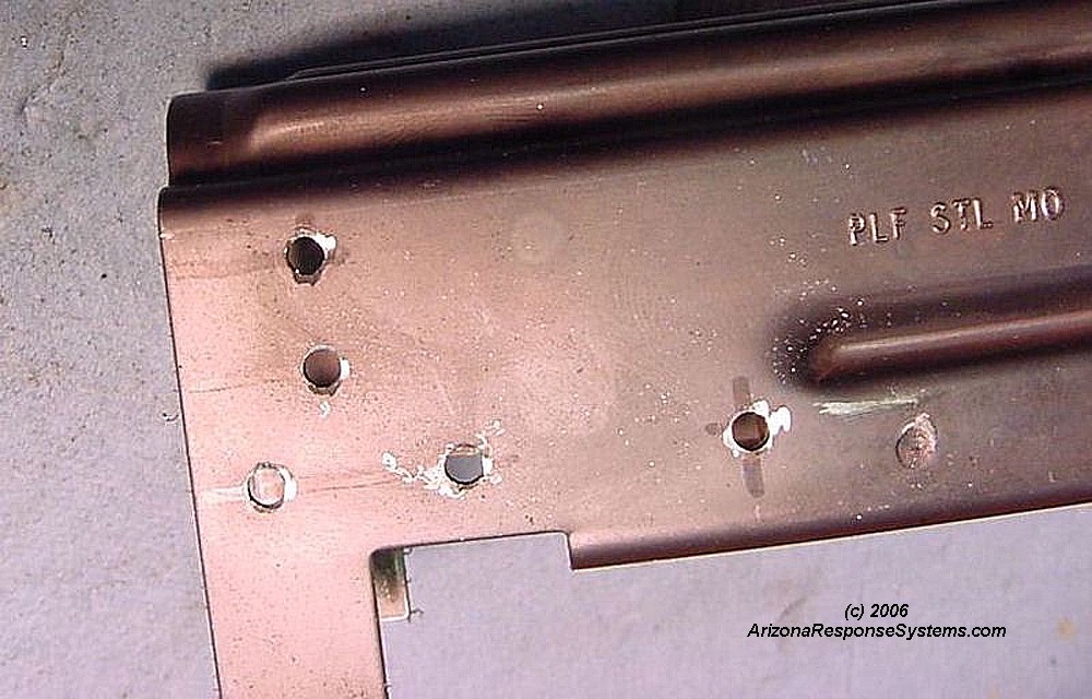
Receiver after drilling the new holes. If you drill the holes slightly undersize (I started with 1/8″), you can then install the trunion and enlarge the holes holes in whatever direction is necessary to more closely align with the old trunion weld marks.
Note how the two tabs are slightly overlapping the front hinge pin support. Trim them slightly to clear.
Another view showing where the tabs must be trimmed. The trunion should be slightly recessed inside the receiver. The recess should be the same depth all the way around the front of the trunion.
Here I have removed the trunion and widened the holes slightly to better align with the old welds on the trunion, and I have deburred both the inside and the outside edges of the holes. At this time, take the bolt and carrier assembly and put it inside the receiver. It should slide easily. If there are any tight spots on the rails, or receiver, they should be sanded and polished now. It is much easier to break the sharp edges on the rails and polish the insides of the receiver when you can access it from both ends. Once you install the trunion, you can only access the inside of the receiver from the rear and bottom.
Lower receiver pinned to upper receiver. I used the largest hole gauge pin that would fit, which was just a tiny bit larger than the original pin. the tape is just to keep it from sliding out. I used the original pin on the rear. This step is critical. If you weld the trunion without locating its position off the lower, you may never get the lower to fit.
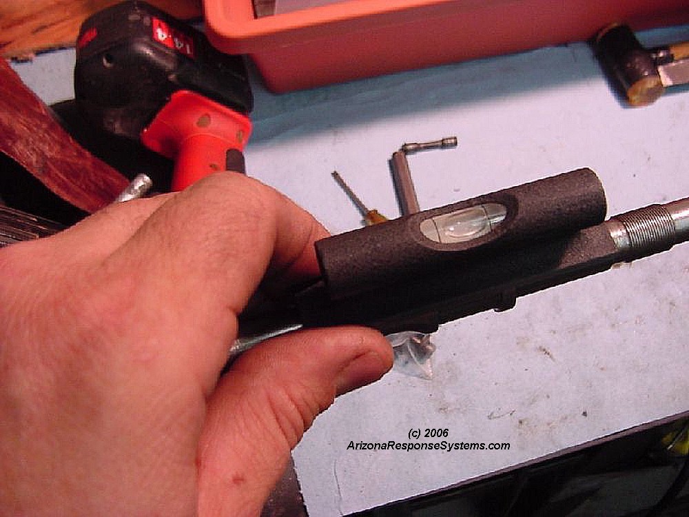
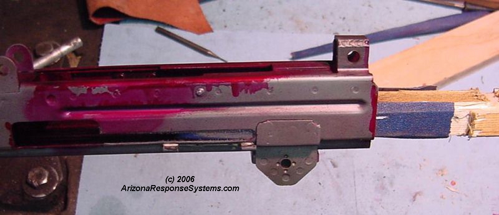
There will be slight vertical play between the trunion and the new receiver. With your original barrel still installed, you can use the flat surfaces on the front sight/gas block to align the barrel and trunion to the receiver. Since a new barrel must have a keyway cut before the gas block is installed, and you cannot position the keyway cut until the barrel is in proper alignment, I added considerable unnecessary time to the build by removing the old barrel prematurely. I indicated the new barrel in my lathe to verify that the bipod grooves were of the same height and parallel. I then used these grooves to level and align the barrel and trunion to the receiver.
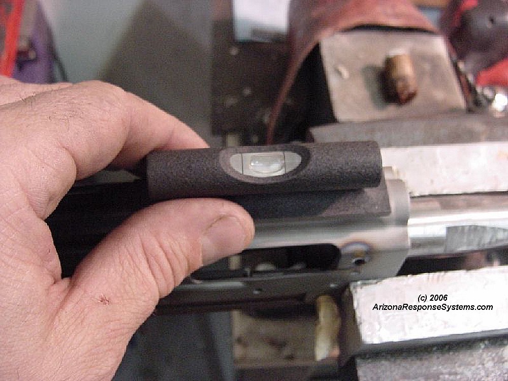
Leveling the back of the receiver.
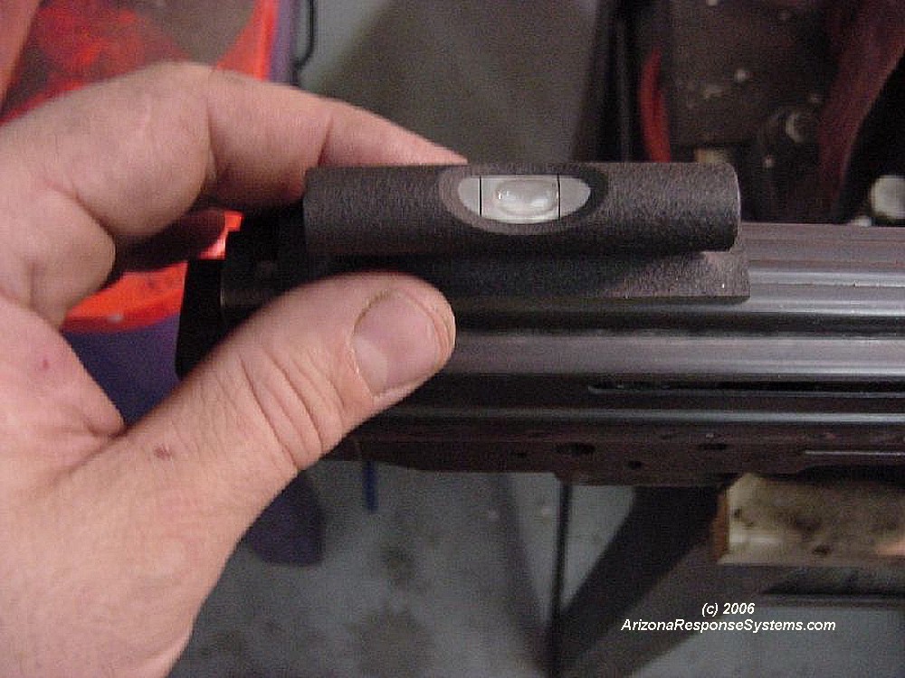
Leveling the front of the receiver. Any time you are dealing with a stamping, there is a possibility of subtle warpage. Therefore it is important to select more than one place on the receiver to insure it is level.
Once you are sure of the alignment, clamp the receiver to the trunion with a welding clamp or C clamp. Insure Bolt carrier slides freely from all angles. Use a tiny tack weld in one hole on both sides to hold in place.
Remove your clamp and insure bolt carrier slides freely from all angles.
Bolt carrier must slide freely and bolt must freely lock and unlock.
Weld Trunion
Clamp receiver to trunion and complete the TIG weld on a second hole, left and right side. This one came out perfectly. allow to cool.
The other side didn’t turn out as nice. I raised the amperage slightly and did it again.
Some of the welds I used too much filler rod and got a lump instead of a neat puddle. Not a problem, but I was hoping every weld would be as perfect as the first so I wouldn’t have to dress down the receiver. Remember to let it cool after each pair of left and right holes.
The welds are functional, but I am not too happy with their appearance. Check after each weld that the bolt carrier still moves freely.
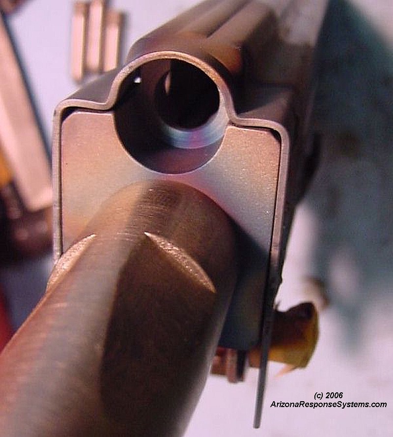
Front view showing the slight recess of the trunion in the receiver
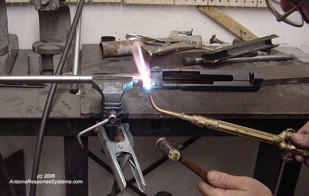
Heating the tabs with an oxygen acetylene torch until they are a dull red, then tapping them around the trunion with a hammer. Allow to cool an then clamp and TIG weld both tabs to the center bottom of the trunion
I ground all of my welds flush. This is okay as-is, but I wanted this gun to resemble the original as closely as possible, so after polishing the receiver sides smooth and sandblasting to clean, I set the TIG welder at a lower amperage to just barely melt the receiver. I then “drew” the spot welds back on.
Spot welds after I drew them back on. You can also see I took a bit more metal off the tabs in trimming than was necessary.
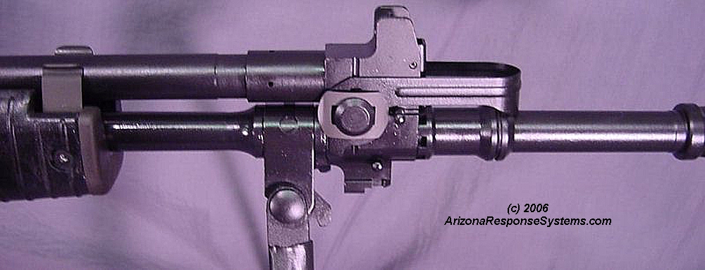
Install Gas Block
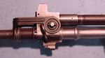
Install the barrel as described earlier. Align the gas block and mark the keyway location at bottom dead center. Transfer the location of the gas port from the old barrel. I measured the distance from the gas block shoulder, and used a pointed scribe in the lathe to mark one axis of the location. On an original barrel, you can determine the top dead center from the barrel flats, but this doesn’t work on the JM Tech barrel, due to the headspacing technique designed into the barrel shoulder.
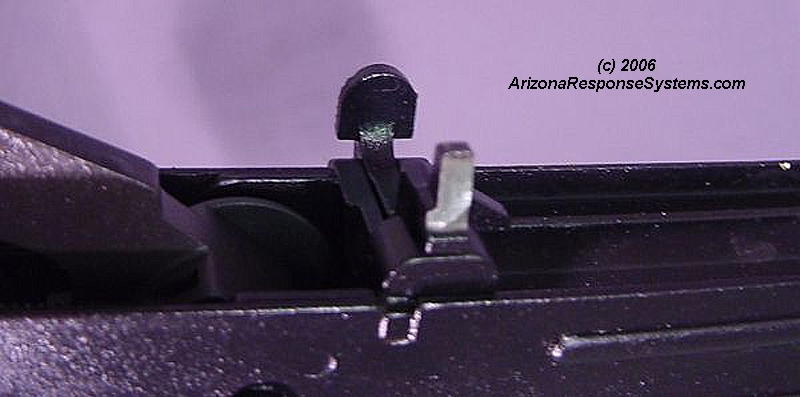
Reassemble the rear sight and align the front sight with the rear sight. I aligned the front sight/gas block and held it in place while a helper scribed bottom dead center off the key on the underside of the gas block. Cut the notch to index the front sight base. Mount the front sight/gas block and using either a mill table (or lathe) index a scribe off the center of the front the front sight, then remove the gas block and scribe the second axis to precisely locate the gas port. There are other ways, but this worked for me. Using the drill bit supplied with the barrel, drill the gas port. After I made the cut, there was just the slightest movement in the front sight block. While this would be clamped by the flash hider assembly, I consider removing the gasblock and front sight for cleaning to be detrimental to accuracy and a weakness of the design. I took a wide, flat punch and tapped both sides of the keyway on the back half, which made the keyway slightly tapered. I then used a small plastic mallet to lightly tap the gas block on, making for the tightest fit – much tighter than the original.
Final Fitting
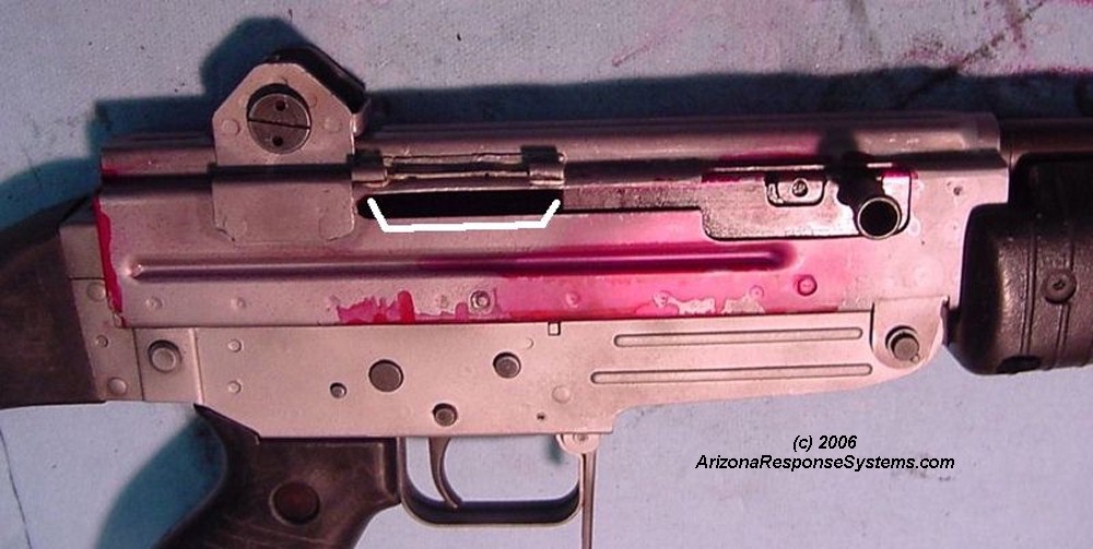
Test fit the bolt carrier for smooth operation. I had a bit of binding in the marked area by the dust cover – perhaps from soldering the bracket.
The bolt hold-open was binding slightly on the inside right receiver rail. I had left the hinge and the bolt hold-open off for testfire so I didn’t discover this binding until after refinish. Testfire for windage. If you have windage deviation that cannot be corrected by moderate rear sight windage adjustment, then your keyway for the sight block may need to be adjusted.
A few file strokes on the bolt hold-open let it move freely.
Sandpaper on a piece of wood took care of any slight binding in the receiver. If I had attached the hinge bracket and the rear sight to the receiver prior to mounting the barrel, polishing would have been easier because I could have approached the tight spot from both sides of the receiver.
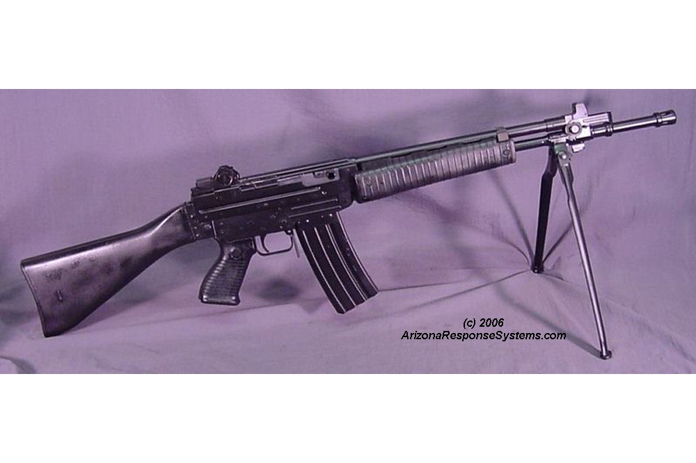
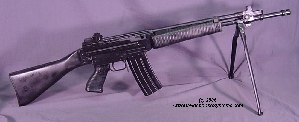
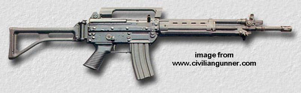
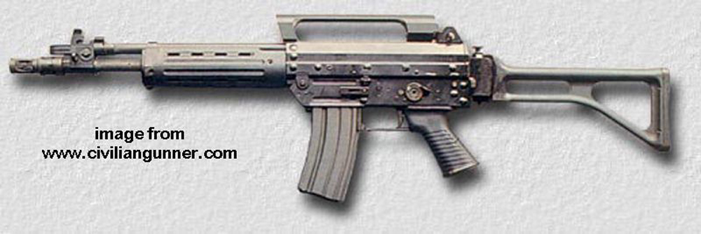
Finished Rifle
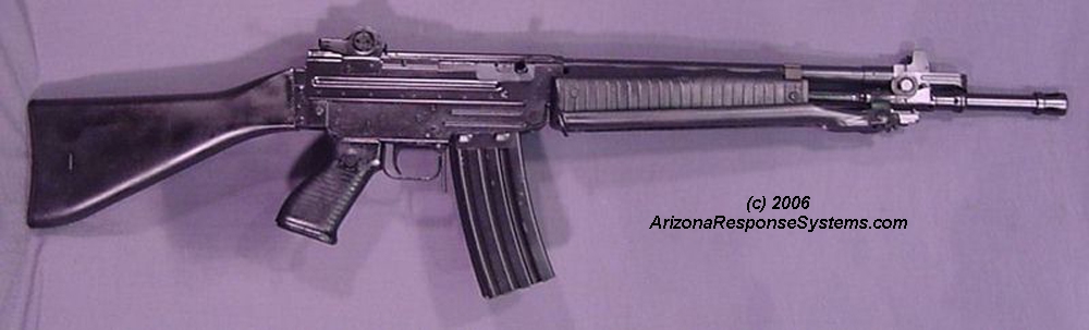
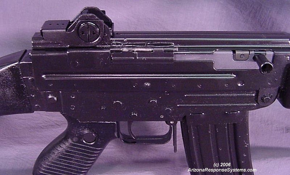
Finished rifle. I testfire a second time after refinish to zero the rifle. Typically, with a 55 grain bullet, a 25 meter zero will also be zeroed at 250 meters.
Finished rifle, closeup. If you are using the Magpul US M16 magazine follower, you may have to cut a small bevel on the back side of the front tabs for it to fit in the AR 70 magazine. The green US M-16 anti-tip follower that I used fit without modification. A steel US magazine floorplate should fit without modification. An aluminum US magazine floorplate, off an M16 magazine, needs the edges thinned slightly as they are thicker than a steel floorplate.
Dustcover bracket was still hesitating slightly and not popping open as it should. If it does not open all the way, it will block the cocking handle and prevent full retraction of the bolt carrier. A tiny area of the bracket was rubbing on the hinge. Once I identified the problem spot, it was easy to fix.
Rear grenade sight lettering filled with white paint.
Front sight block is stainless steel and won’t take a phosphate finish, but it can be painted or colored with black oxide.
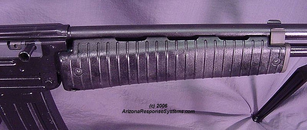
Handguards pivot of the front hinge pin and attach to the gas tube spring tension
Additional AR-70 Notes
AR-70/90 with short barrel.

Leave a Reply
You must be logged in to post a comment.