HK Tutorial: Build a JLD PTR-91 HK Clone
(updated 04-09-2020)
Introduction
JLD Enterprises purchased the HK equipment from FMP (Portugal) to manufacture HK G3 type receivers in the USA. The company changed organization and is now PTR-91.
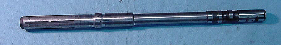
Trunion
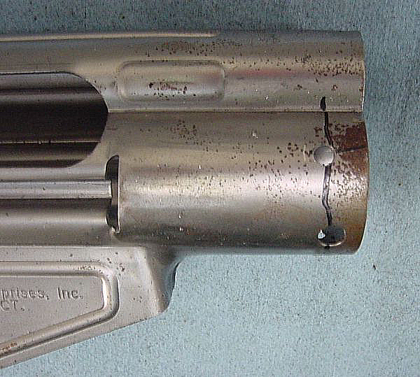
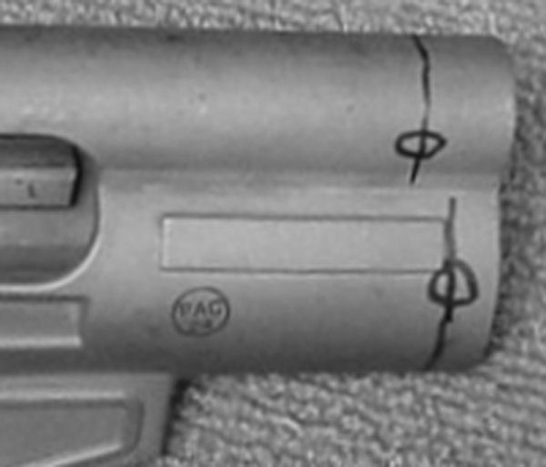
PTR-91 receiver after drilling the holes for the spot welding. The location isn’t critical, but cosmetically its nice for them to align and be spaced symmetrically.
bottom two holes, far enough away from the receiver weld that you won’t grind the receiver weld if you have to resurface these two welds.
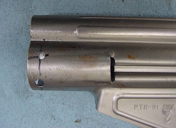
The drill bit walked a little bit toward the rear of the receiver as I drilled this hole. As I weld it, I will make my circles spiraling slightly forward so the finished weld is more in line with the barrel pin hole.
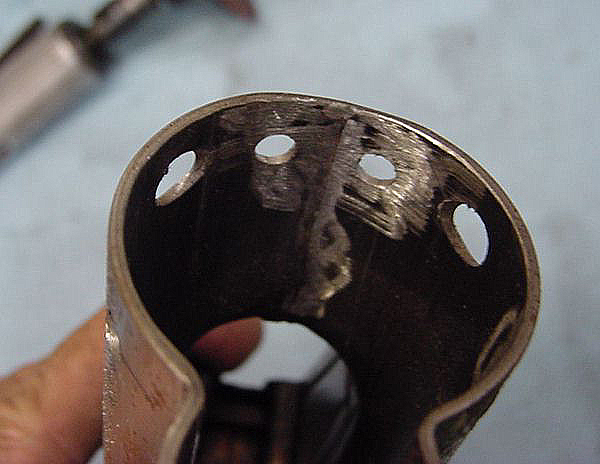
You may need to deburr the receiver weld at the bottom inside of the receiver, as well as deburr the edges of your holes. that way the trunion will slide in smoothly.
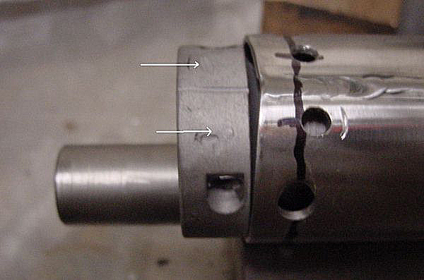
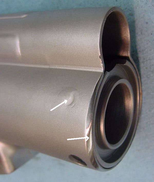
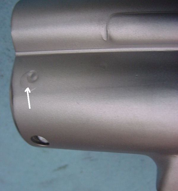
The arrows indicate where the old welds were on this trunion.
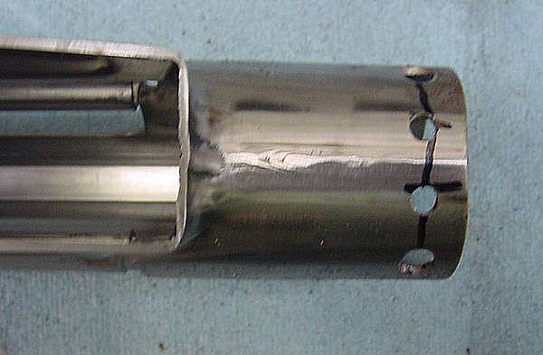
I used a cut-off barrel section, turned to the receiver diameter, to keep the trunion aligned vertically in the receiver prior to welding.
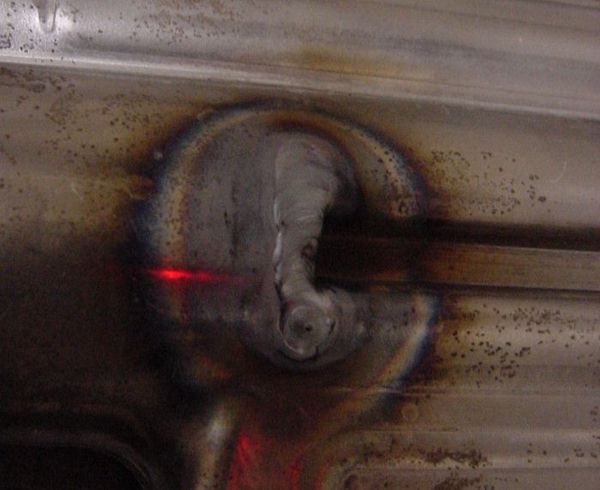
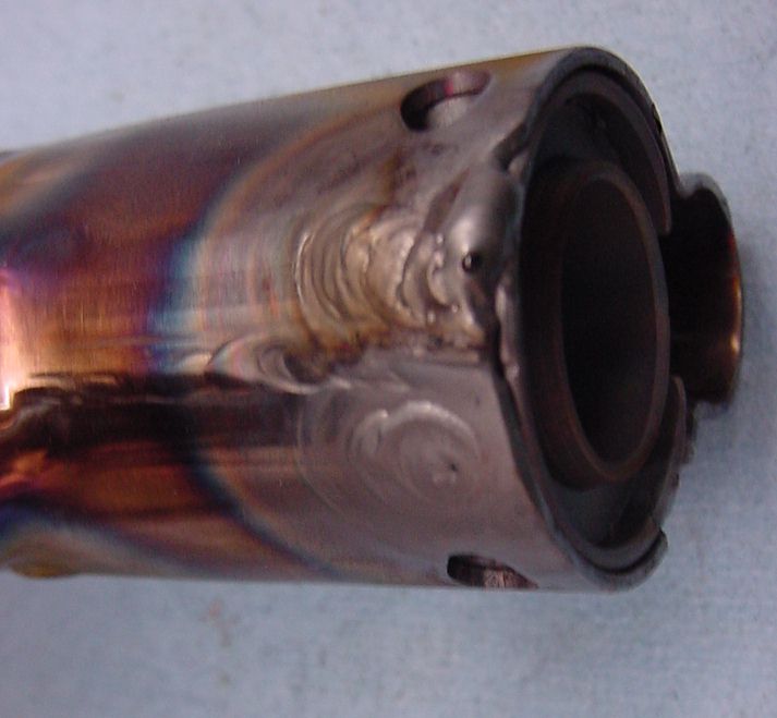
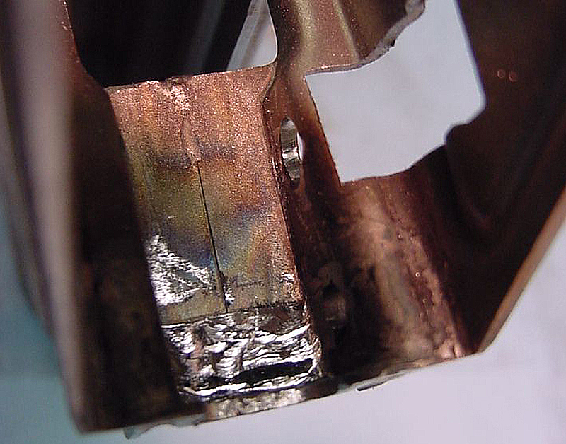
Here is the rear of the trunion showing through the slot in the receiver. YOu must will this slot with weld.
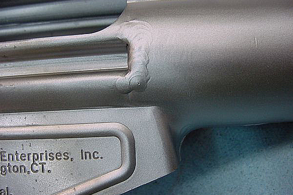
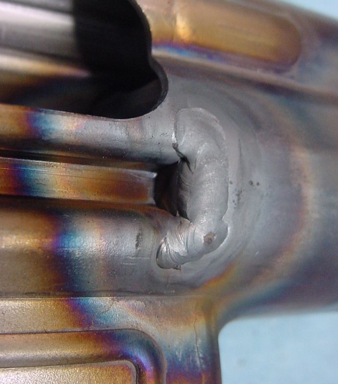
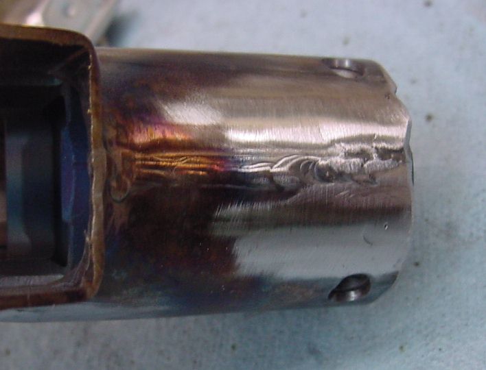
I am satisfied with this weld. Using a TIG welder with argon shield at 75 amps, and only bringing the amperage all the way up to 75 on the thick part of the trunion, and dropping it down with the foot pedal as I reached the thinner receiver area, I obtained good penetration of the trunion without burning through the receiver.
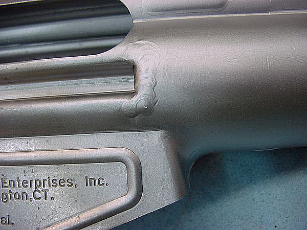
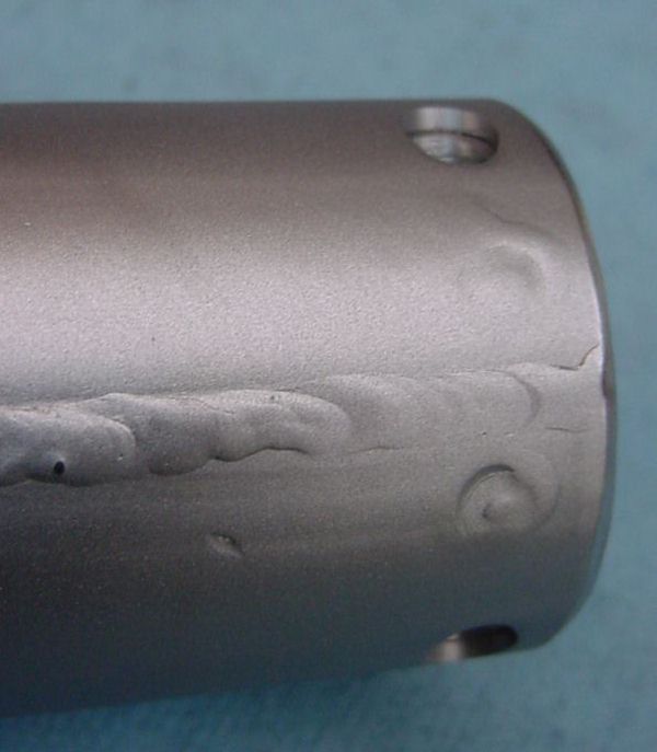
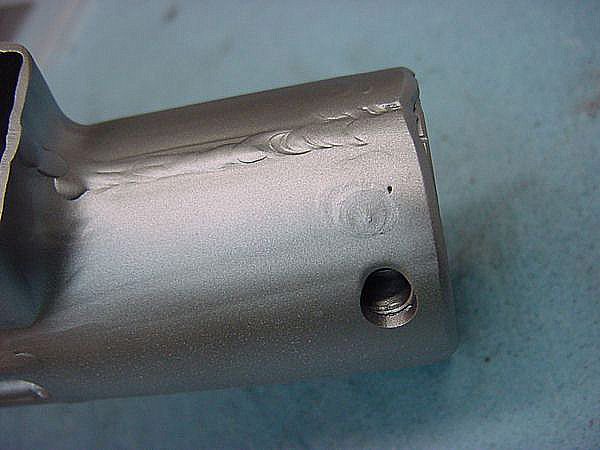
Here is the same weld after bead blasting. I use bead blasting to see what the surface will look like after I apply METACOL III Satin Black
Make sure your weld covers the rear face of the trunion as well as the side.
I’m pretty happy with this weld. After I deburr the edge, the appearance will be a slightly recessed weld with no raised edges.
Another good weld. If I had to nitpick, I’d say “a little more filler rod” but its pretty good as it is.
Another good weld.
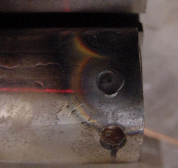
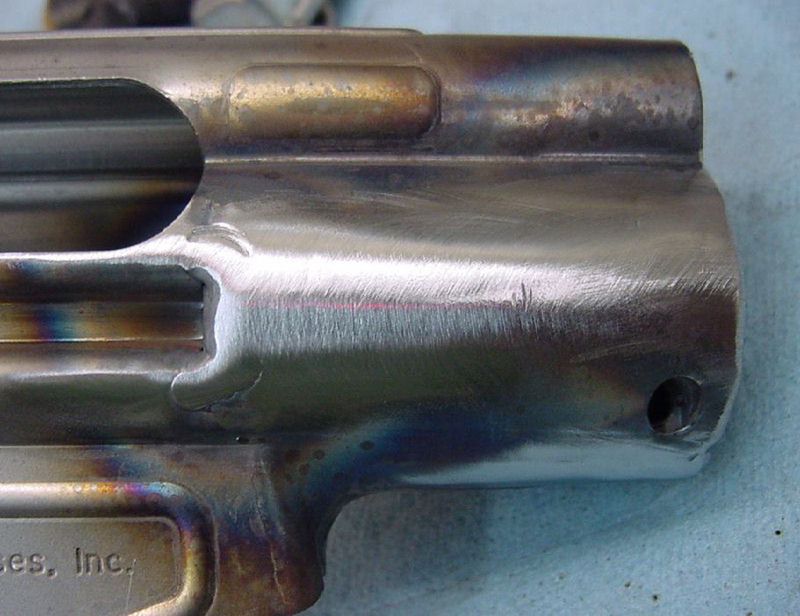
After dressing down, I am not too happy with this weld. while totally functional,. it is not visible enough – it is too smooth. I will go back over it with the TIG and “draw” a circle of molten metal . Note how I chamfered the front of the receiver.
These are also acceptable welds. I will probably redraw the top one.
I’m pretty happy with this one, although I didn’t dress down my spillover quite enough – the depth and location of the weld hole is fine.
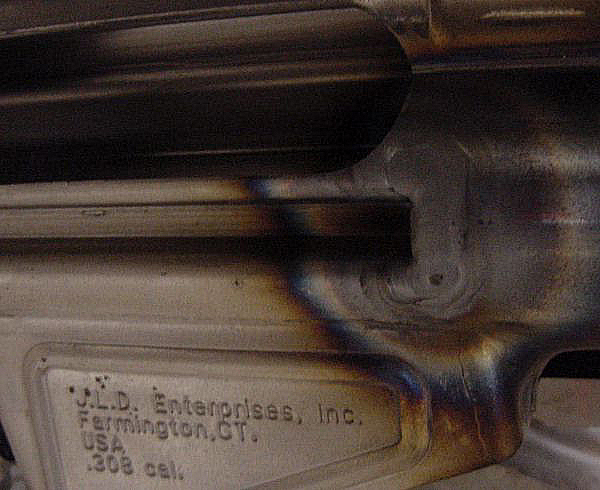
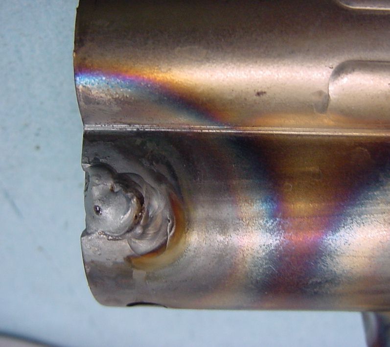
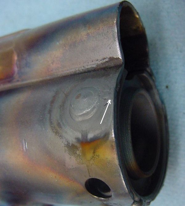
Here is a bad weld. I didn’t get the trunion hot enough before moving the electrode, so the surrounding metal began flowing into joint. I “burned through” the receiver. What I should have done was to increased the amperage on the weld, and held it at one spot until the trunion started to puddle, then added my filler rod and pulled the surrounding receiver into the puddle. What was happening was I was putting hot filler rod onto a cooler trunion. The trunion , being thicker, takes longer to heat. I also had contaminated my electrode which caused uneven arcing. All is not lost. Its ugly, but can be fixed. I corrected my mistake and filled in all the low points. Next, I will grand and sand it smooth.
Same problem with this weld. if you “dip your wick” and contaminate the electrode, take the time to stop and regrind the tip. This bad weld was a combination of dirty electrode, holding the electrode too far off 90 degrees, and moving to the receiver wall before the trunion absorbed sufficient heat for the filler rod to flow well.
I am happy with this weld. It is functional and cosmetically appealing. however it sits higher (more filler rod) then the weld on the other side. For symmetry, I am going to grind the welds flat and then redraw them.
Using a disc sander and 100 grit paper, followed by a medium 3M Scotchbrite disc, I smoothed out my bad weld.
Here are the bottom welds after grinding the excess off, sanding smooth, and then “drawing” the weld back on.
Here is another hole where I burned through to the front of the receiver. I rewelded it, dressed it smooth, and then redid my weld. you can still see a spot where I repaired the burn through. I will have to do it one more time, as the weld is sitting too high, but at least the location and shape is correct.
While this weld was perfectly functional, I used a bit too much filler rod and it sat higher than the weld on the other side. For symmetry, I ground it down for “drawing”
Cocking Tube
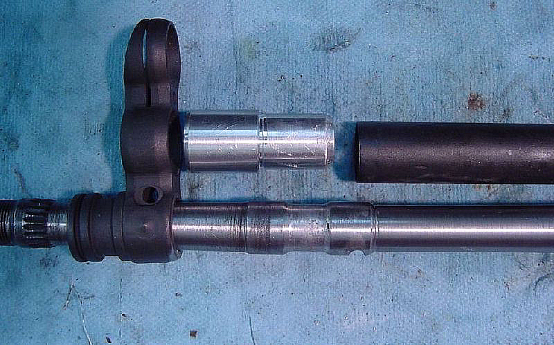
Aluminum fixture for aligning cocking tube to triple frame
Triple frame temporarily installed and centered
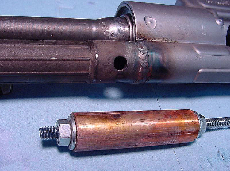
The cocking tube is relatively thin, and its inner liner is very thin and easy to burn through. I made a copper rod as a backing plate (weld does not easily stick to copper/brass).
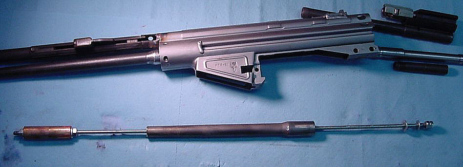
I put the copper section on a piece of all-thread rod. Since the copper shield can still get stuck in the tube, I put a cut-off barrel section onto the rod as well to use as a pull-hammer. If the rod gets stuck, I slam the barrel section a few times against the nut and washer on the end of the rod to pop the shield out of the tube.
I replaced the aluminum triple-frame aligning fixture with this one, made from a flash hider on a barrel section. I needed it longer to sit on my welding fixture.
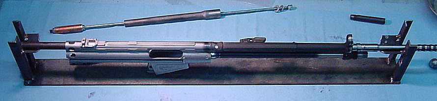
I had trouble getting the weld around the tube 180 degrees and keeping it in a straight line, so I made this fixture on which I can “hang” the parts and rotate the work while holding the welder in one spot. The hammer and end washer are removed from the copper plate and the all-thread is slitting inside the barrel section that acts as my rear axle. Its still not perfect, but it makes for smoother welds than I was obtaining trying to to rotate the rifle by hand.
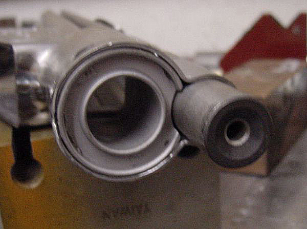
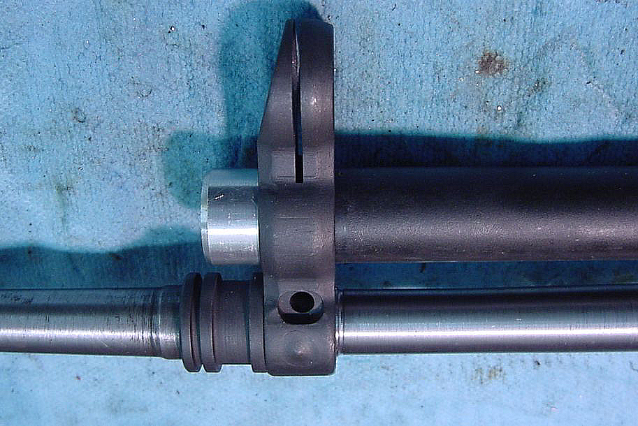
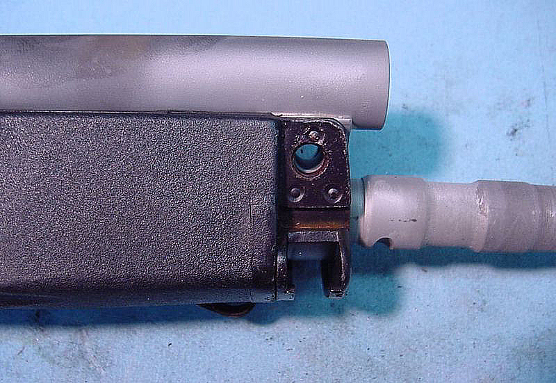
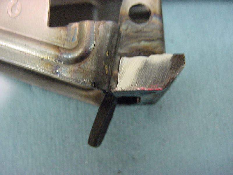
This is a critical fit. the gap between the cocking handle extension and the front of the bolt carrier, with the bolt carrier closed and locked, must be no more than .022″ – the thickness of a box cutter blade. the minimum gap is slight contact, as long as the cocking handle can still wiggle. If the gap is too large, pulling the handle out will not unlock the rollers.
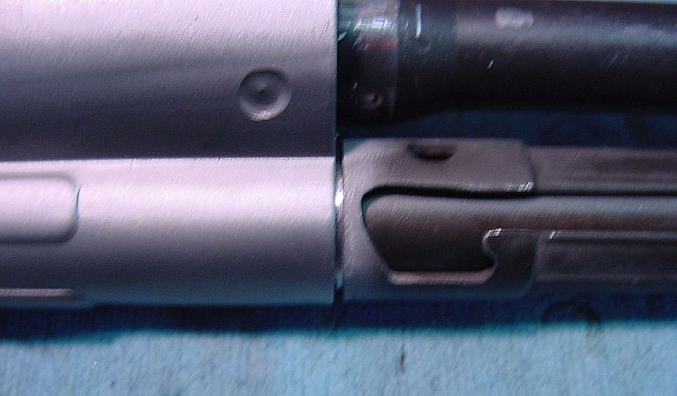
Ready to weld. the hardest part is right at the bolt-hold open cutout on the cocking tube. it is very easy to burn through this thin spot.
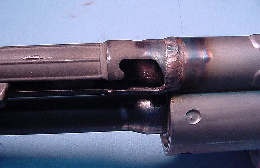
Completed weld
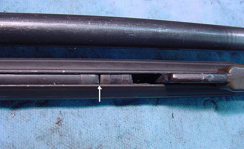
Triple Frame
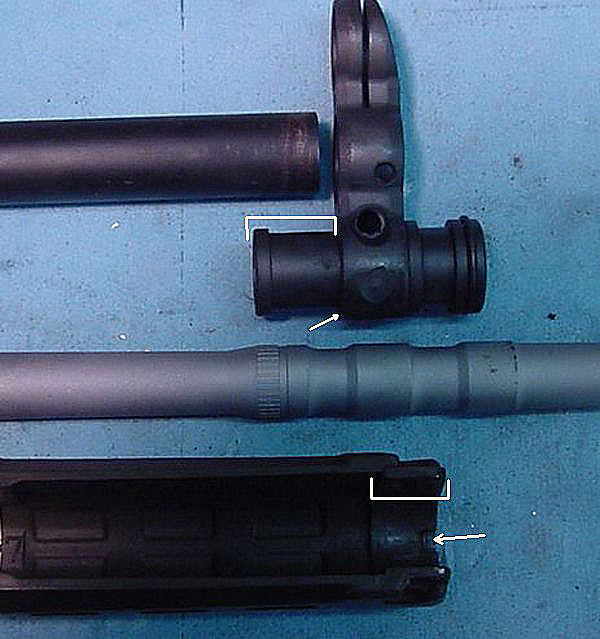
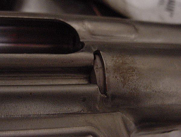
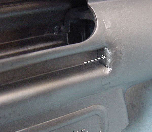
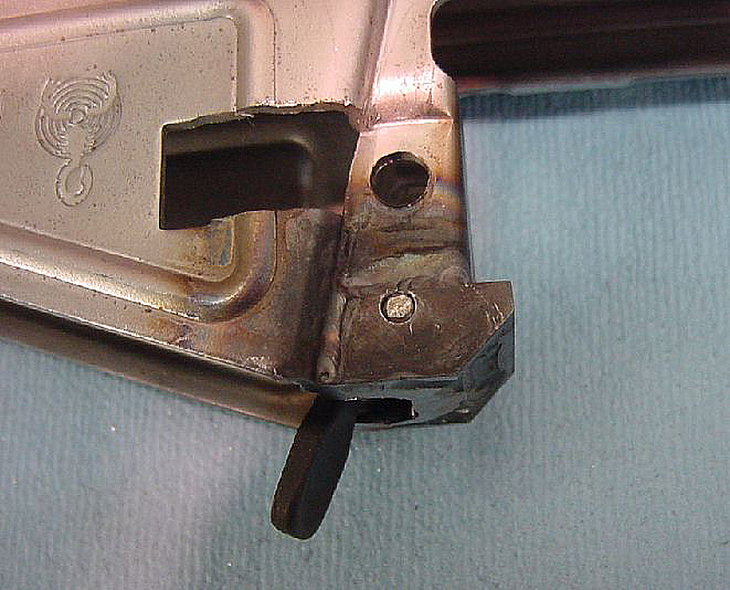
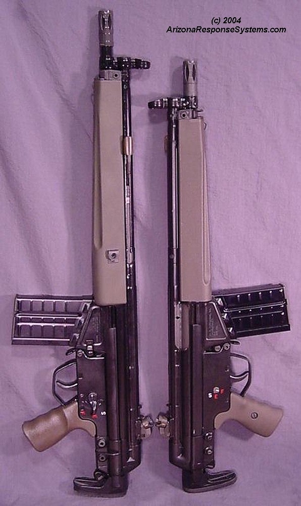
The rear ring on the triple frame is for the narrow handguard. the front of the handguard slides over the ring and the key fits into the key way (arrow). The handguard pin sits on top of the barrel. To use a wide handguard, you must remove the triple frame ring.
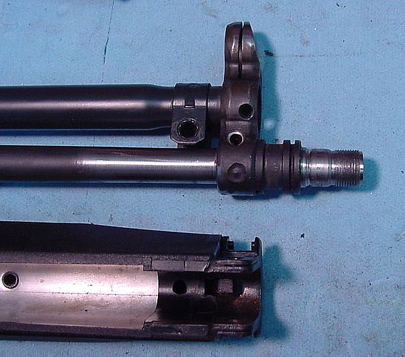
The wide handguard uses a tapered cocking tube with a handguard hanger. Note the taper on the barrel compared to the previous picture.
Handguard Hanger
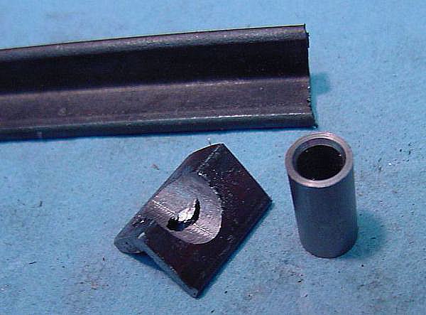
Non-tapered cocking tubes are incompatible with wide handguards because they do not have a hanger for the front of the handguard may attach. I make hangers from scratch, using a small piece of angle iron and a small pice of steel tubing
Test-fitting the two parts.
I cleaned the pieces by sandblasting and then silver soldered them with Silvaloy 35% silver solder

Same picture after sandblasting off the stray flux
Using an old handguard to align the hanger on the cocking tube.
Soldering the hanger

Sandblasting the solder clean
Confirming fit with wide handguards
Paddle Magazine Catch
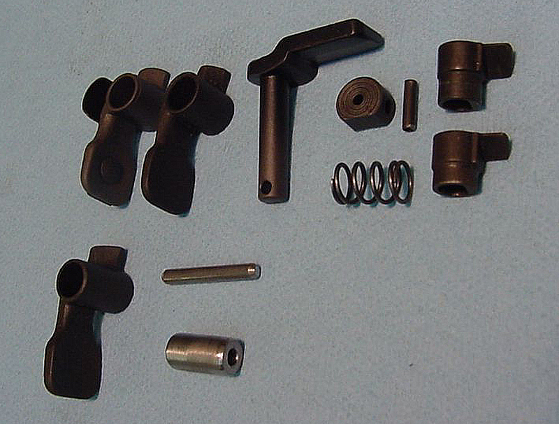
There are several types of paddle magazine catch. German guns use a narrow catch. Spanish (CETME), Portuguese, PTR-91s (Portuguese tooling) and Springfield Armory (Greek) have a wider sleeve on the magazine catch. Late German have a narrower sleeve and a piece of sheet metal inside the magazine well on either side. Within the German, there are the original, an “anti-rattle” with a leaf spring on it, and a roller + leafspring, where the camming surface has been replaced with a paddle.
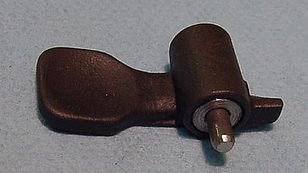
Traditionally, the paddle magazine catch is attached by a hollow sleeve. Unfortunately, this hollow sleeve is also the mechanism for attaching a full-auto “swing down” trigger group. BATFE has determined that modifying a receiver to take the original sleeve, since it also will accept a swing-down trigger group, is manufacturing a machinegun – something that is unlawful in most circumstances. The BATFE approved method for installing a paddle is to use an undersize axle pin, thereby preventing the “temporary” hole from becoming a machinegun. I manufacture a sleeve with a 1/8″ diameter axle pin. The sleeve fits inside the paddle.
The most tedious part of the paddle magazine well conversion is removing the shelf from inside the magazine well. This shelf was installed to block the hole that would allow a “swing down” machinegun trigger pack. The part of the shelf inside the magazine well must be removed. Be careful not to break through the thin sheet metal on the underside of the magazine well where the shelf attaches. If you do, it can be filled with low-temp silver solder.
Inside of the magazine well after I have removed the shelf.
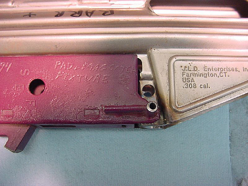
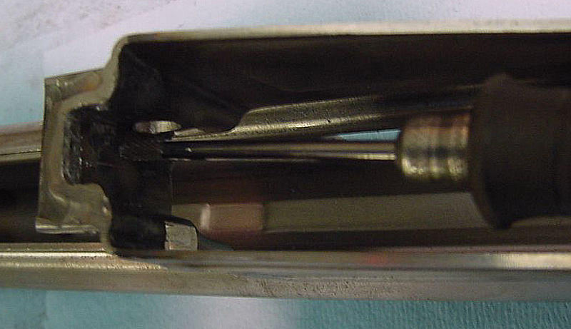
Here is my drilling fixture. Its pretty worn at this time. Eventually I will replace it with one that will permit me to replace the drill-bit bushings without replacing the entire unit. Basically, its a trigger group, “clipped and pinned (see the “clip & pin” section). I then soldered into the front push-pin hole a bushing with a 1/8″ inner diameter. You must have the trigger mechanism housing inside the box to establish the correct height.. Drill the hole all the way through one side and almost, but not quite through the other side. (there is some debate on drilling all the way through).
Paddle magazine catch inserted with axle pin. you can now trim the axle pin to rest just below flush. Test fit your magazine for fit, and the paddle for complete range of motion.
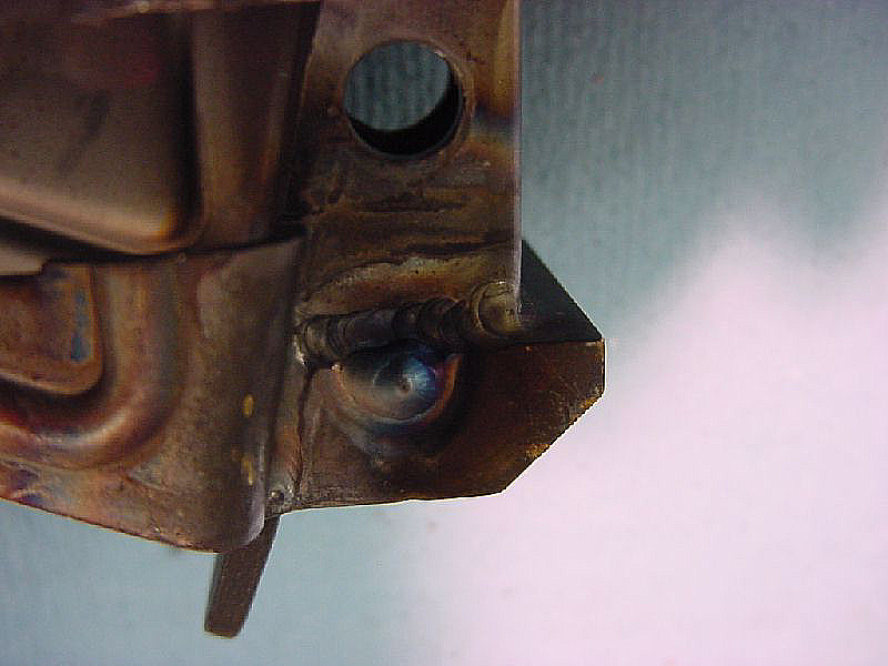
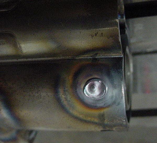
TIG welding the end of the pin
Grinding the weld flush.
Finished Rifle
Finished rifles.
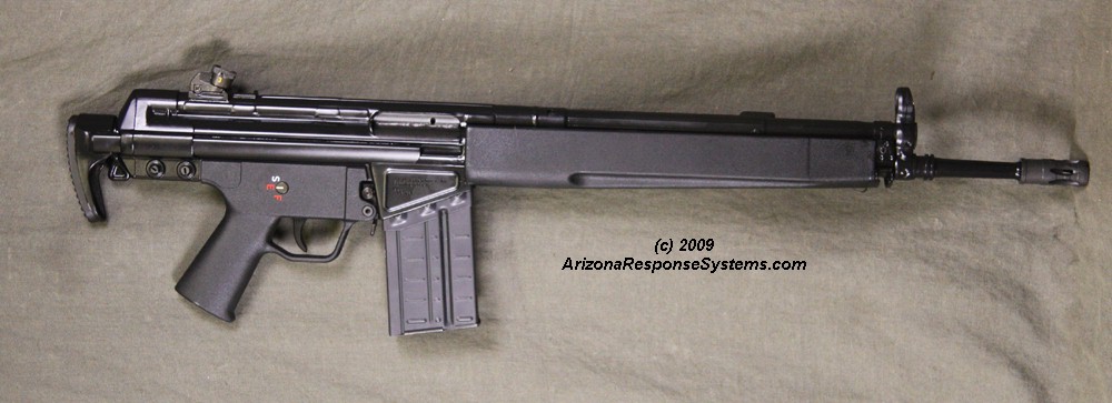
Finished rifle.
Leave a Reply
You must be logged in to post a comment.