HK Tutorial: Build an SW3 HK Clone
(updated 04-09-2020)
Introduction
I first prepared this photographic documentation of an HK G3 clone in early 2001. I wouldn’t dream of doing it again. The Special Weapons SW3 stainless steel cast receiver (also sold as a Century Arms International) is simply not close enough to original specifications to bother with. At the time, the SW3 and a few less common Portuguese “FMP” receivers were the only options. Now with the excellent JLD Enterprises PTR-91 stamped receiver (manufactured in the USA on FMP equipment) readily available, the dramatically substandard SW3 is no longer worth the effort.
Furthermore, In the years I have been building HK clones, I have come up with some imp[roved and simplified methods on which I will elaborate. The processes are still the same – just a difference in details. This step-by step guide can be of assistance to some who wish to build their own clone.
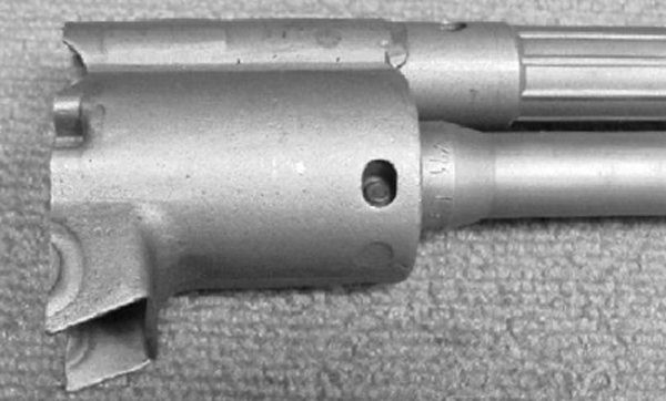
Trunion
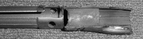
Original FMP trunion in cut-off receiver section. There are two methods for building a clone, which are determined by whether or not your receiver already has the trunion installed. If the trunion is already installed, then you must press the barrel out of the old trunion, and press it into the new trunion while setting the bolt gap. Roller locking guns like the HK do not use traditional headspace – rather the “bolt gap” or the distance between the bolt and the carrier when locked, is measured. In the case of a receiver such as the one in this example, where the trunion is not installed, the bolt gap is already set by the relationship of the barrel to the old trunion. The old trunion is removed from the receiver section and reinstalled in the new receiver. This picture shows the spot-welds that attach the trunion to the receiver.
Spotwelds on the bottom of old receiver section.
Spotwelds on the side of the old receiver section.
Sandblasting the receiver section – I like a clean work area to prevent surprises.
Drilling out the old spot welds.
Cutting the bottom weld on the receiver stud. This does not go through to the trunion and allows the old receiver stub to be peeled off the trunion.
Old trunion after cleaning up weld spots.
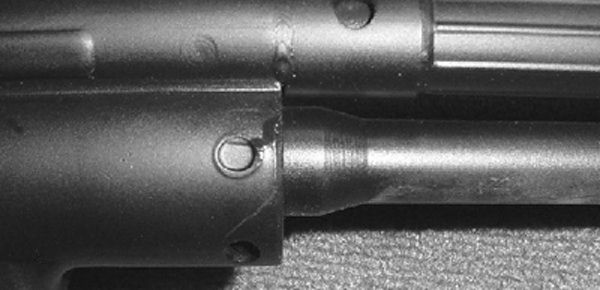
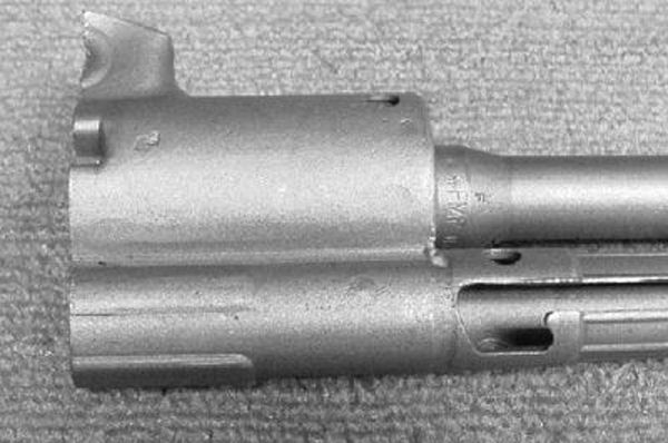
Barrel
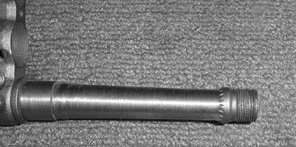
At the time of this build, the 1994-2004 Assault Weapons Ban was in effect, requiring the removal of the grenade-launcher ring from the barrel.
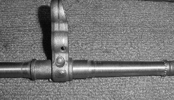
Note the rectangular tab on the bottom rear of the triple frame. This fits into a slot on the narrow handguards, but must be removed to use wide handguards.
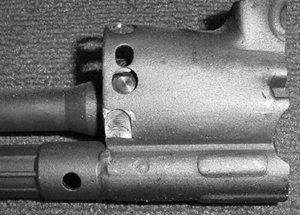
Test fitting alignment of triple frame – it does not contact the cocking tube. While there are several methods of aligning, and often “top dead center” does not guarantee the gun will shoot straight, generally some tape to center the triple frame works.
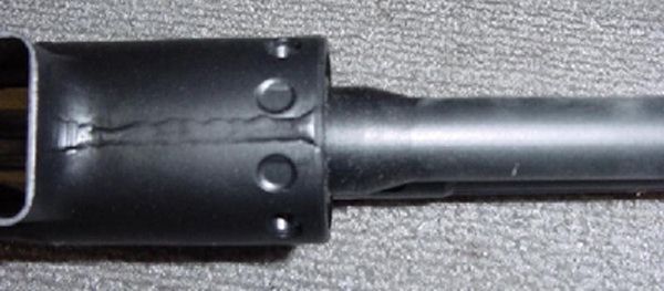
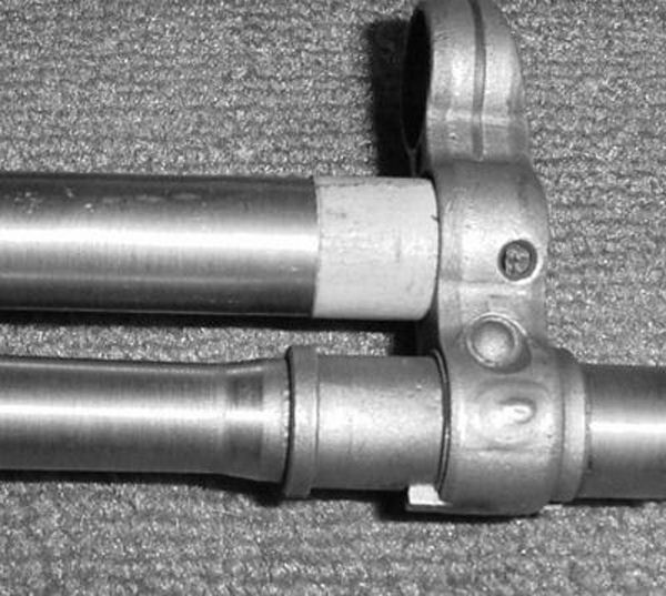
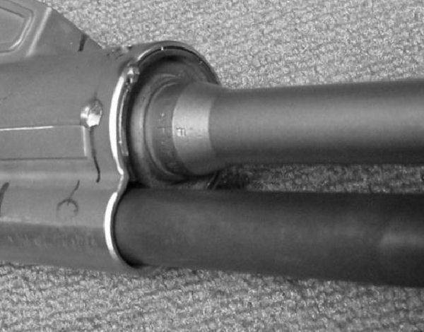
Cocking Tube
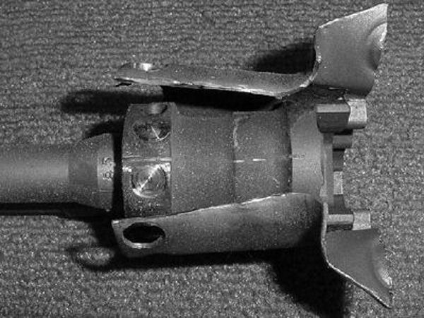
I messed this cocking tube up. There is a thin sleeve inside the cocking tube that you should not cut through. It is a challenge remove the cocking tube from the old receiver stub without cutting through the sleeve, but the sleeve has a dual purpose of shielding the subsequent weld from dripping into the tube, and also to align it with the receiver.
Cutting through the tube forced me to fabricate a brass heat sink and do extra polishing after the weld. You must test fit the tube with the cocking handle and bolt carrier installed. There must be a gap between the cocking handle extension and the bolt carrier, but it can be no more than .020″ – about the thickness of a box-cutter blade. If the gap isn’t there, the cocking handle extension becomes an impact surface for the bolt carrier returning forward. If too great, the rollers won’t fully unlock during the camming action of the cocking handle extending outward and retracting the bolt carrier will be stiff.
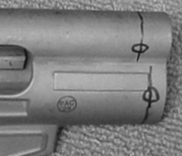
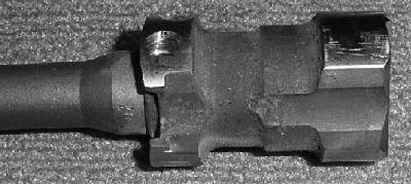
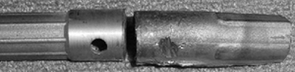
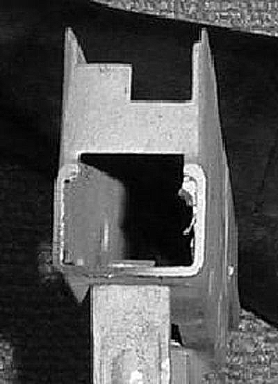
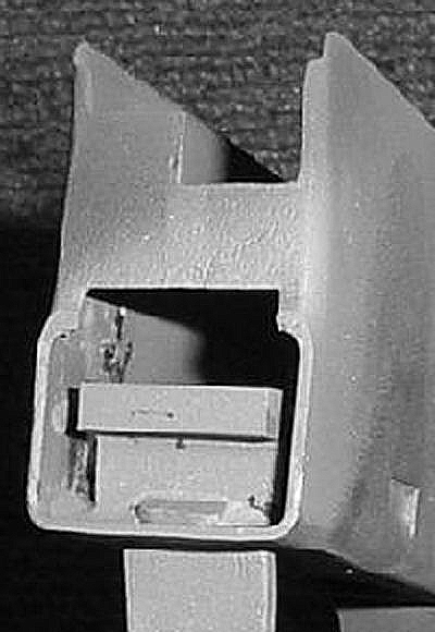
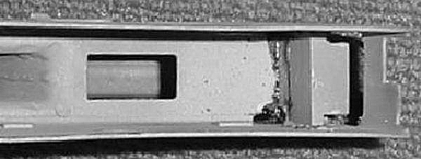
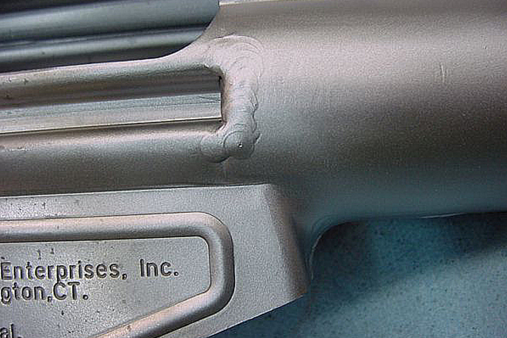
SW3 Receiver
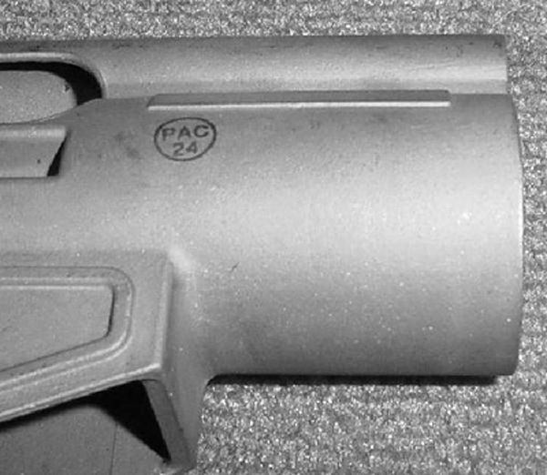
The SW3 stainless receiver.
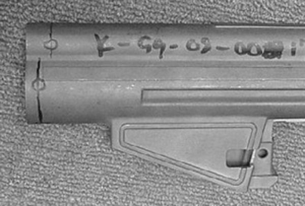
Marking locations of holes for welding.
Marking location of holes for welding.

Marking location of holes for welding.
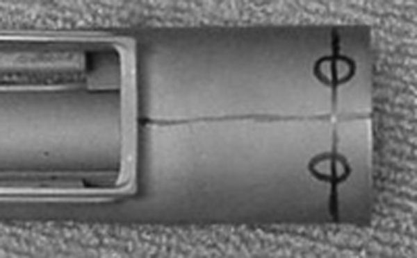
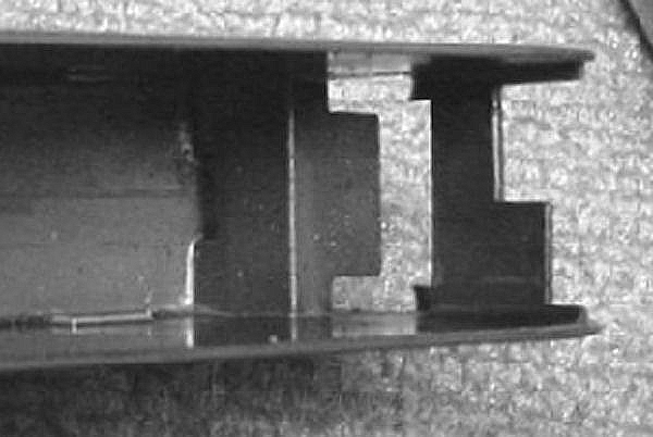
Holes drilled. setting trunion flush with receiver. I use a small tack weld to hold it in place.
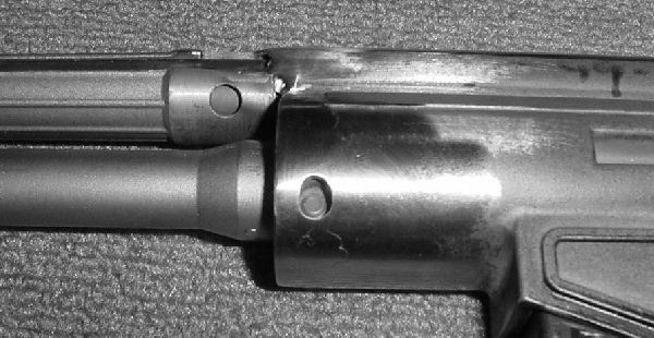
Holes welded through to trunion and dressed. Cocking tube welded.
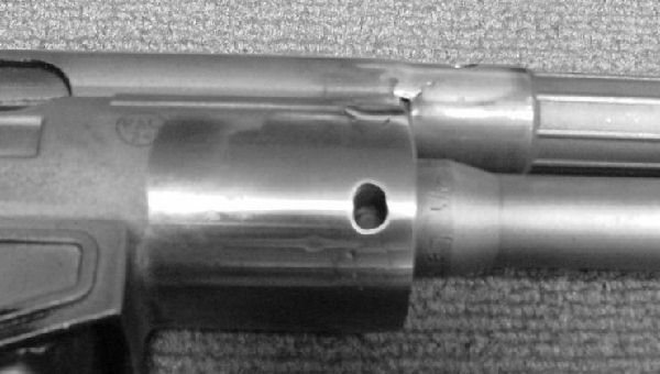
Cleaning up welds.
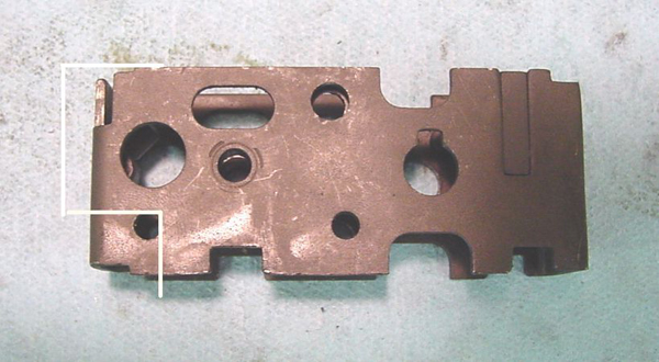
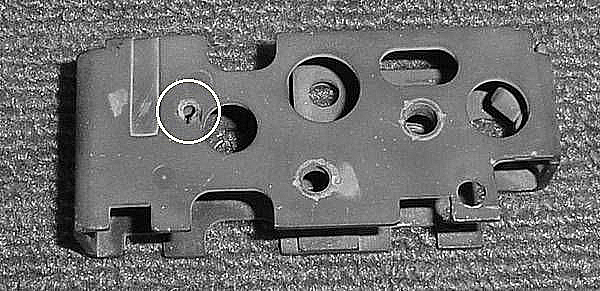
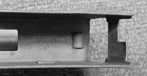
Sear Roller
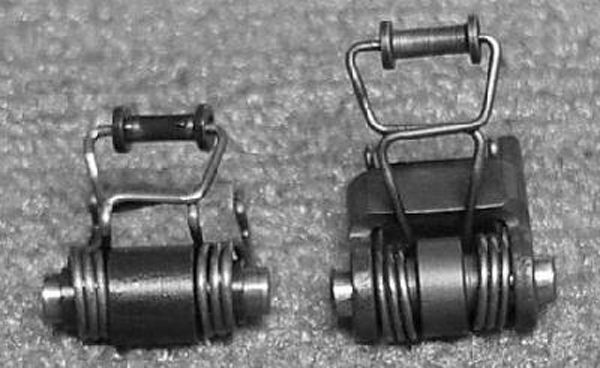
The full auto sear spring also functions as spring for the full-auto safety sear. When converting to semiauto, the safety sear is omitted, leaving the steps in the sleeve in the wrong place.
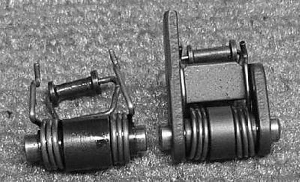
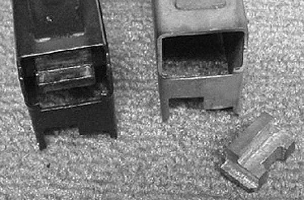
Another view showing difference between semi and full auto sleeve.
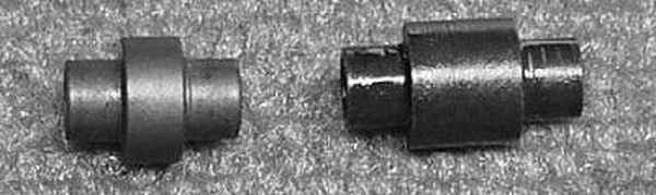
Fullauto (L) and semiauto (R).
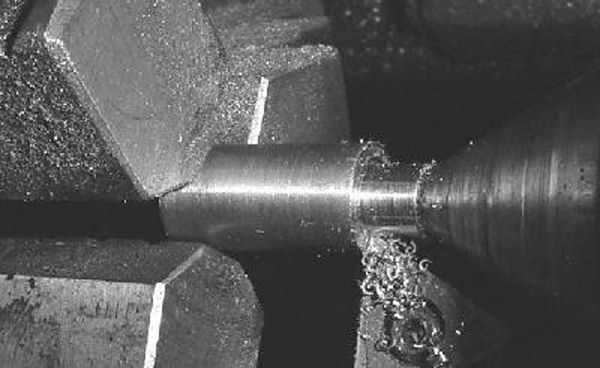
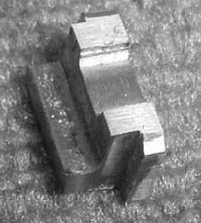
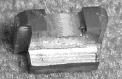
Lathe turning a new sleeve.
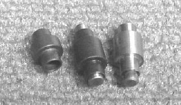
Fullauto sleeve (L), semiauto original sleeve (C), and new semiauto sleeve (R).
Trigger Mechanism Housing
Cutting the trigger mechanism housing to clear the semiauto receiver and grip frame shelves.
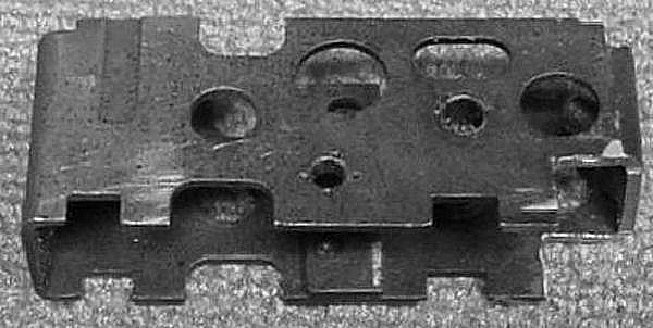
Not shown is the plate welded over the cut, while not absolutely necessary, it makes the unit more rigid and is “factory correct”.
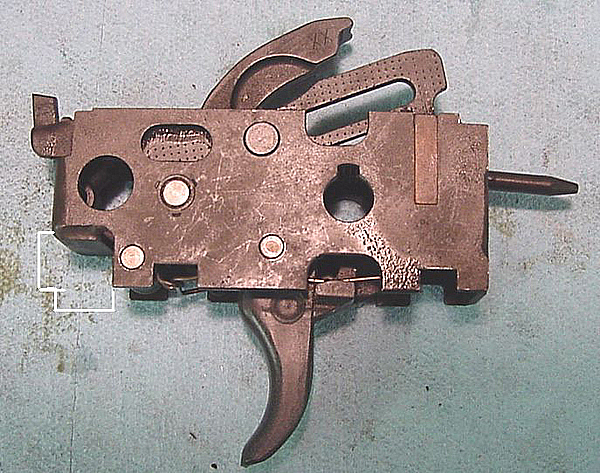
Plate welded over the cut – this is from a 9mm assembly.
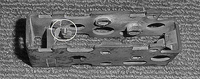
There is a stop in the mechanism housing to limit the trigger travel. On full-auto, the trigger has a longer sleep. Installing a pin below the full-auto stop will enable the sear to always catch and disconnect the trigger.
Another view of the pin installed.
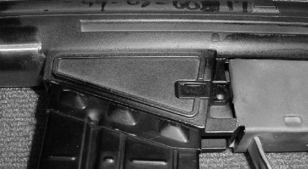
Grip Frame Shelf
Semiauto shelf for installation into grip frame.
Another view.
Sandblasted prior to welding.
Grip Frame

The grip frame
Cutting the tabs off the grip frame. Now I use a technique called “clipping and pinning” where I machine out the area but leave the tabs in place, then cut the ends off a pin and solder the ends to make a “fake” swing-down lower. On semi-auto guns, the hole where this 3rd pin would go is blocked, as it would allow the use of a standard machinegun trigger pack.
Testing location of shelf.
New shelf compared to factory semiauto grip frame.
Fabricated grip frame shelf installed. Now I use a much simplified method of brazing a plate to coincide with the shelf height.
Welded in place.
Cleaning up welds. The height of the shelf is critical. If there is vertical play, then the ejector may come too low and miss the cartridge.
Shows the relationship of the grip frame shelf to the grip frame and magazine well.
Stock Assembly
fitting the stock ferrule. I also removed the numbers from the ferrule. This is one area where the SW3 is particularly out-of-spec. A lot of fitting was required to get it to install smoothly and for the pin holes to line up correctly.
Leave a Reply
You must be logged in to post a comment.